


Lenovo G460e/G560e Hardware Maintenance Manual
46
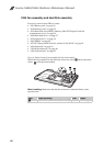
1090 Fan assembly and Heat Sink assembly
For access, remove these FRUs in order:
• “1010 Battery pack” on page 34
• “1020 Dummy card” on page 35
• “1030 Hard disk drive(HDD)/Memory/Mini PCI Express Card slot
compartment cover” on page 36
• “1040 Hard disk drive” on page 37
• “1050 Optical drive” on page 39
• “1060 DIMM” on page 40
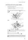
• “1070 PCI Express Mini Card for wireless LAN/WAN” on page 41
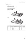
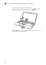
• “1080 Keyboard” on page 43
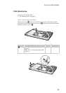
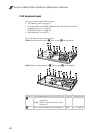
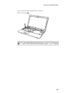
• “1100 Keyboard bezel” on page 48
• “1110 System board” on page 53
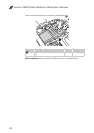
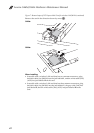
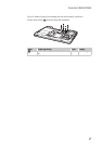
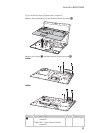
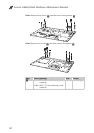
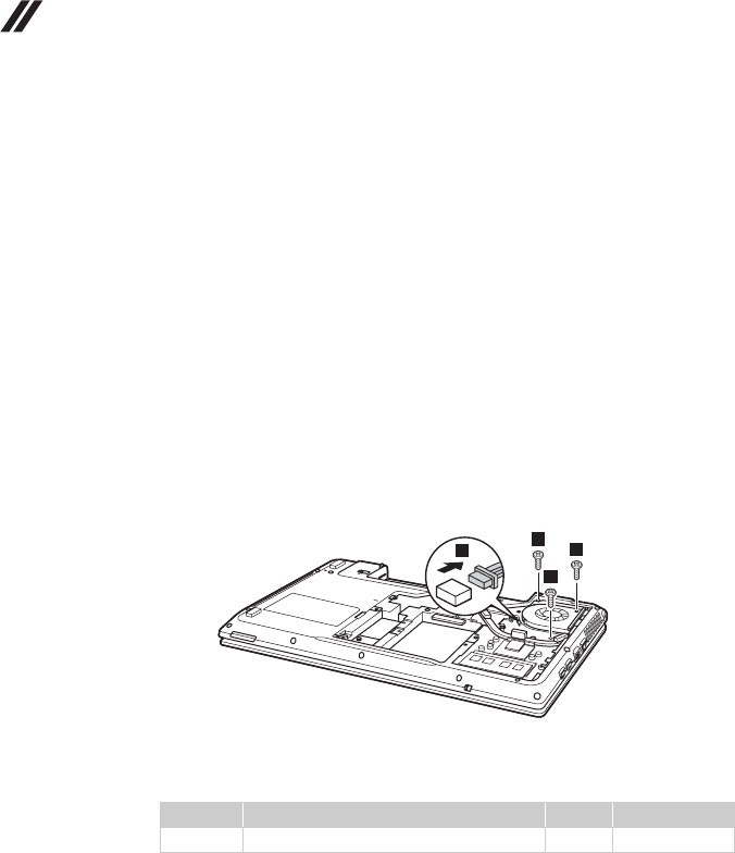
Figure 9. Removal steps of fan assembly and heat sink assembly
Detach the fan connector in the direction shown by arrow and loosen three
screws to lift the fan assembly.
When installing: Make sure that the fan connector is attached firmly to the
system board.
Step Screw (quantity) Color Torque
M2.5 × 4 mm, flat-head, nylok-coated (3) Black 1.5 ~ 2.0 kgfcm
a
b
2
2
2
1
a