


Lenovo G460e/G560e Hardware Maintenance Manual
66
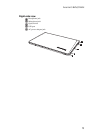
1160 LCD panel, LCD cable and hinges
For access, remove these FRUs in order:
• “1010 Battery pack” on page 34
• “1020 Dummy card” on page 35
• “1030 Hard disk drive(HDD)/Memory/Mini PCI Express Card slot
compartment cover” on page 36
• “1040 Hard disk drive” on page 37
• “1050 Optical drive” on page 39
• “1060 DIMM” on page 40
• “1070 PCI Express Mini Card for wireless LAN/WAN” on page 41
• “1080 Keyboard” on page 43
• “1100 Keyboard bezel” on page 48
• “1110 System board” on page 53
• “1120 LCD unit” on page 57
• “1150 LCD front bezel” on page 64
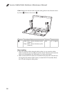
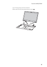
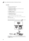
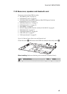
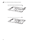
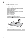
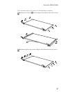
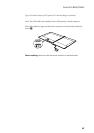
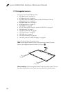
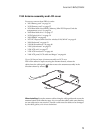
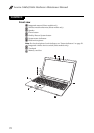
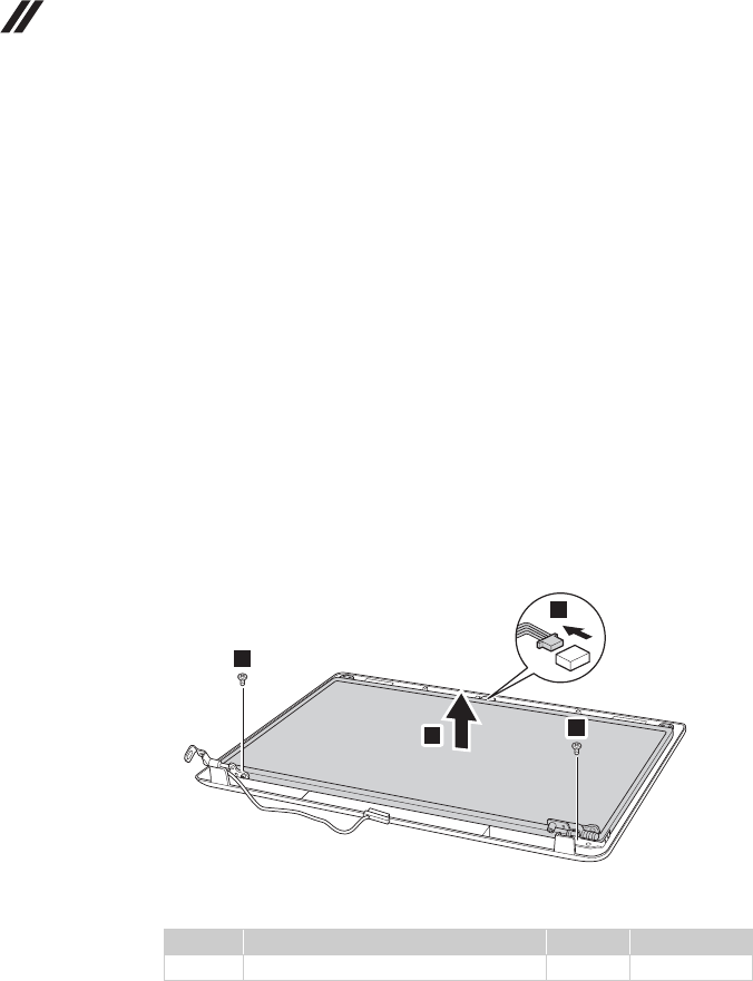
Figure 16. Removal steps of LCD panel, LCD cable and hinges
Remove two screws . Unplug the integrated camera connector in the direction
shown by arrow . Lift the LCD panel in the direction shown by arrows .
When installing: Make sure that the connector is attached firmly.
Step Screw (quantity) Color Torque
M2.5 × 5 mm, flat-head, nylokcoated (2) White 2.0 ~ 2.5 kgfcm
a
b
c
1
1
2
3
a