


Backplane for server models with 12 3.5-inch hard disk drive bays
This topic provides information to help you locate the connectors on the backplane for server models
with 12 3.5-inch hard disk drive bays.
The following illustrations show the connectors on the backplane for server models with 12 3.5-inch hard
disk drive bays.
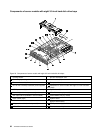
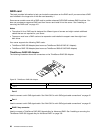
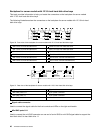
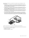
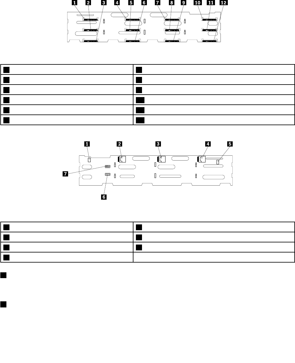
Figure 30. Front view of the backplane for server models with 12 3.5-inch hard disk drive bays
1 Slot 0 for a 3.5-inch hard disk drive 7 Slot 6 for a 3.5-inch hard disk drive
2 Slot 1 for a 3.5-inch hard disk drive 8 Slot 7 for a 3.5-inch hard disk drive
3 Slot 2 for a 3.5-inch hard disk drive 9 Slot 8 for a 3.5-inch hard disk drive
4 Slot 3 for a 3.5-inch hard disk drive 10 Slot 9 for a 3.5-inch hard disk drive
5 Slot 4 for a 3.5-inch hard disk drive 11 Slot 10 for a 3.5-inch hard disk drive
6 Slot 5 for a 3.5-inch hard disk drive 12 Slot 11 for a 3.5-inch hard disk drive
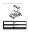
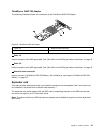
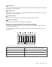
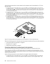
Figure 31. Rear view of the backplane for server models with 12 3.5-inch hard disk drive bays
1 Signal cable connector 5 Signal cable connector
2 Mini-SAS ports 8-11
6 8-pin power connector
3 Mini-SAS ports 4-7
7 8-pin power connector
4 Mini-SAS ports 0-3
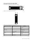
1 Signal cable connector
Used to connect the signal cable for the front controls and LEDs on the right rack handle.
2 Mini-SAS ports 8-11
Used to connect the mini-SAS connector on one end of a mini-SAS to mini-SAS signal cable to support the
hard disk drive 8 to hard disk drive 11.
40 ThinkServer RD430 User Guide