


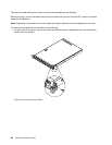
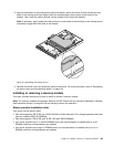
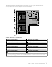
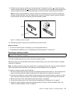
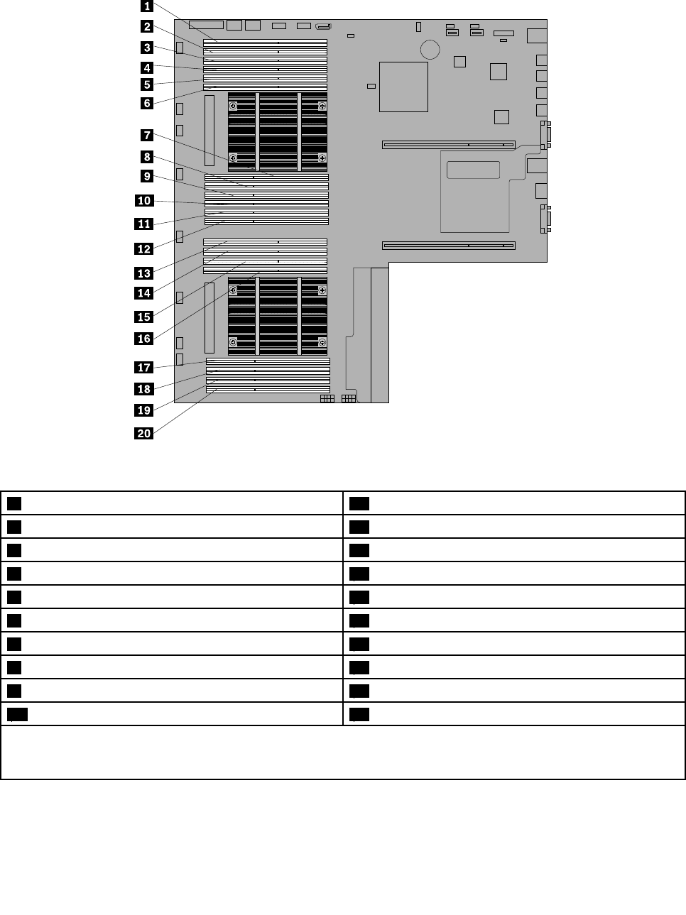
The following illustration shows the locations of all memory slots on a system board that has two
microprocessors (also known as CPUs) and two heat sinks installed.
Figure 33. Memory slots on the system board
1 Memory slot (CPU1 DIMMC1) 11 Memory slot (CPU1 DIMMA2)
2 Memory slot (CPU1 DIMMC2) 12 Memory slot (CPU1 DIMMA1)
3 Memory slot (CPU1 DIMMC3)* 13 Memory slot (CPU2 DIMMC1)
4 Memory slot (CPU1 DIMMD1) 14 Memory slot (CPU2 DIMMC2)
5 Memory slot (CPU1 DIMMD2) 15 Memory slot (CPU2 DIMMD1)
6 Memory slot (CPU1 DIMMD3)* 16 Memory slot (CPU2 DIMMD2)
7 Memory slot (CPU1 DIMMB3)* 17 Memory slot (CPU2 DIMMB2)
8 Memory slot (CPU1 DIMMB2) 18 Memory slot (CPU2 DIMMB1)
9 Memory slot (CPU1 DIMMB1) 19 Memory slot (CPU2 DIMMA2)
10 Memory slot (CPU1 DIMMA3)* 20 Memory slot (CPU2 DIMMA1)
Note: Your server supports up to 8 LV RDIMMs when one microprocessor is installed and up to 16 LV RDIMMs
when two microprocessors are installed. If you are using LV RDIMMs, do not install them into any of the memory
slot with a * mark in this table.
Chapter 6. Installing, removing, or replacing hardware 71