


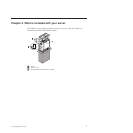
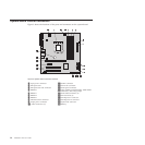
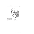

System-board internal connectors
Figure 3 shows the locations of the parts and connectors on the system board.
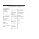
1 4-pin power connector 11 eSATA connector
2 Microprocessor 12 Power fan connector
3 Microprocessor fan connector 13 Front panel connector
4 DIMM 2 14 Clear CMOS (Complementary Metal Oxide
Semiconductor) /Recovery jumper
5 DIMM 1 15 Front USB connectors (2)
6 DIMM 4 16 PCI card slots (2)
7 DIMM 3 17 PCI Express x1 card slot
8 Thermal sensor connector 18 PCI Express x16 card slot
9 24-pin power connector 19 System fan connector
10 SATA connectors (3) 20 Battery
Figure 3. System board connector locations
14 Installation and User Guide