


42
IdeaPad U260 Hardware Maintenance Manual
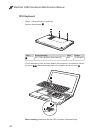
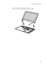
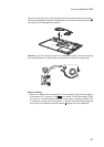
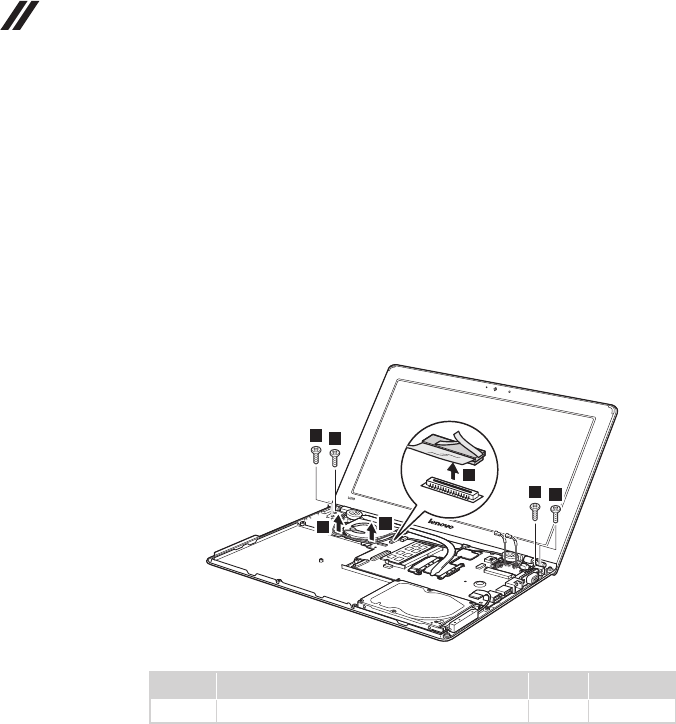
1050 LCD unit
For access, remove these FRUs in order:
• “1010 Keyboard” on page 34
• “1020 Keyboard bezel” on page 35
• “1030 Battery pack” on page 39
• “1040 PCI Express Mini Card for wireless LAN” on page 40
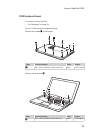
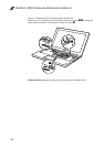
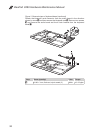
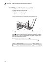
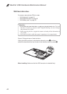
Figure 5. Removal steps of LCD unit
Unplug the LCD connector in the direction shown by arrow
1
. Remove four
screws
2
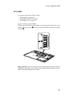
. Release the LCD cable from the cable guides in the direction shown
by arrows
3
.
1
2
2
2
2
3
3
Step Screw (quantity) Color Torque
2
M2.5 × 5 mm, at-head, nylok-coated (4) Black 1.5~2.0 kgfcm
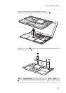
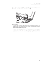
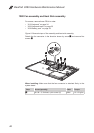
When installing:
Route the antenna cables along the cable guides. As you route the cables, •
make sure that they are not subjected to any tension. Tension could cause
the cables to be damaged by the cable guides, or a wire to be broken.
Make sure that the LCD connector is attached rmly and make sure that you •
do not pinch the antenna cables when you attach the LCD assembly. Route
the LCD cable along the cable guides.