


40
Lenovo IdeaPad U300e Hardware Maintenance Manual
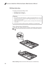
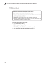
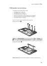
1060 Fan assembly and Heat Sink assembly
For access, remove these FRUs in order:
• “1010 Base cover” on page 33
• “1020 Battery pack” on page 35
• “1030 Hard disk drive” on page 36
• “1050 PCI Express Mini Card for wireless LAN” on page 38
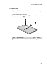
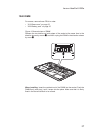
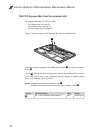
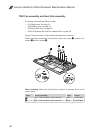
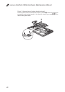
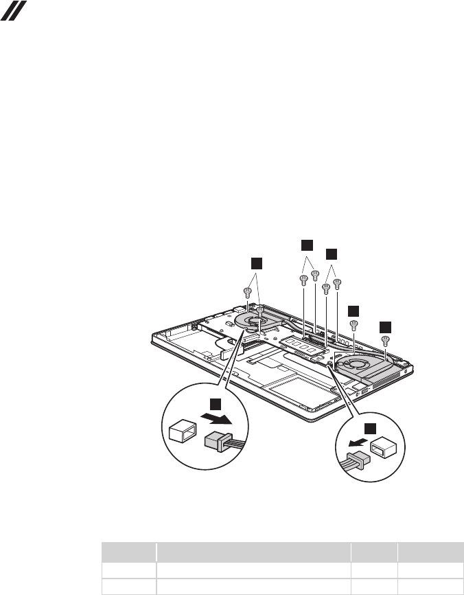
Figure 6. Removal steps of fan assembly and heat sink assembly
Detach two fan connectors in the direction shown by arrows
1
, remove four
screws
2
and four screws
3
.
2
2
3
3
3
1
1
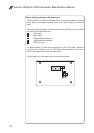
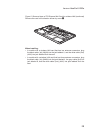
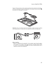
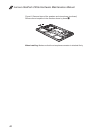
When installing: Make sure that the fan connector is attached firmly to the
system board.
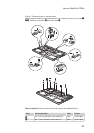
Step Screw (quantity) Color Torque
2
M2 × 3 mm, at-head, nylok-coated (4) White 1.5 ± 0.2 kgfcm
3
M2 × 4 mm, at-head, nylok-coated (4) Black 1.5 ± 0.2 kgfcm