


48
Lenovo IdeaPad U300e Hardware Maintenance Manual
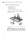
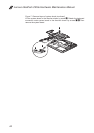
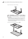
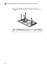
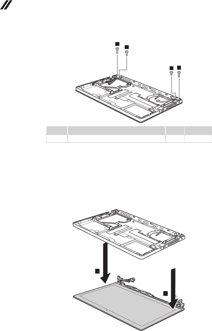
Figure 9. Removal steps of LCD unit (continued)
2
2
2
2
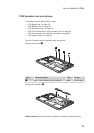
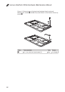
Step Screw (quantity) Color Torque
2
M2.5 × 6 mm, at-head, nylok-coated (4) Black 3.0 ± 0.2 kgfcm
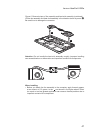
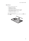
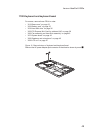
When installing:
Route the antenna cables along the cable guides. As you route the cables, •
make sure that they are not subjected to any tension. Tension could cause
the cables to be damaged by the cable guides, or a wire to be broken.
Make sure that the LCD connector is attached rmly and make sure that you •
do not pinch the antenna cables when you attach the LCD assembly. Route
the LCD cable along the cable guides.
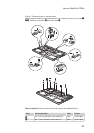
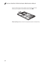
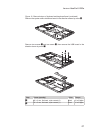
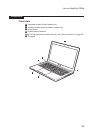
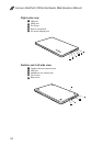
Remove the LCD unit in the direction shown by arrows
3
.
3
3