


Lenovo IdeaPad U510 Hardware Maintenance Manual
56
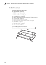
1130 Base cover, USB board, bluetooth card, power board and
speakers
For access, remove these FRUs in order:
• “1010 Keyboard” on page 34
• “1020 Battery pack” on page 36
• “1030 Dummy card” on page 40
• “1040 Hard disk drive” on page 41
• “1050 Optical drive” on page 43
• “1060 PCI Express Mini Card for wireless LAN/WAN” on page 44
• “1070 SSD Card” on page 46
• “1080 Low-frame module” on page 47
• “1090 Fan assembly and Heat Sink assembly” on page 49
• “1100 DIMM” on page 50
• “1110 System board” on page 51
• “1120 LCD unit” on page 54
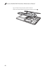
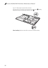
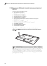
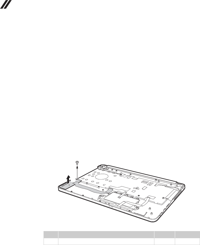
Figure 13. Base cover, USB board, bluetooth card, power board and speakers
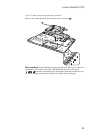
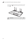
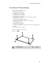
Remove screw , and then remove the USB board in the direction shown by
arrow .
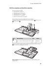
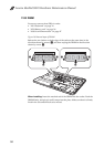
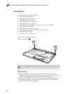
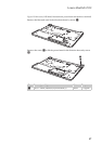
When installing: When attaching the USB board to the base cover, adjust the
placement of the USB jacks as shown , and make sure that both of the USB jacks
are attached to the holes on the base cover as shown. Improper placement of the
jacks might cause a damage.
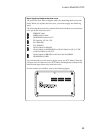
Step Screw (quantity) Color Torque
M2.5 × 4 mm, flat-head, nylok-coated (1) Black 2.5 kgfcm
a
b
b
a
a