


Lenovo IdeaPad U510 Hardware Maintenance Manual
62
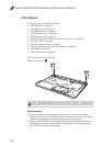
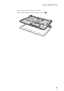
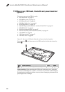
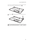
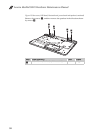
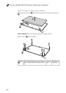
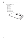
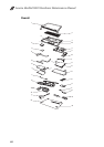
Figure 15. LCD panel, LCD cable and hinges (continued)
Disconnect the connector , lift the LCD panel in the direction shown by arrow
.
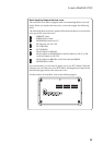
When installing: Make sure that the connector is attached firmly.
Remove screws and the hinges.
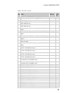
Step Screw (quantity) Color Torque
M2.0 × 3.0 mm, flat-head, nylok-coated
(2)
Black 1.8 kgfcm
b
c
c
b
d
d
d
d
d
d
d
c