


206-4119
9
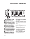
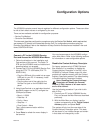
Installing CodePlus Transcoder Cards
HCS6600
SERVICE
PORT
RESET
STATUS
ASI OUT
I
E
E
E
I
E
E
E
1
3
9
4
B
1
3
9
4
A
HCS6600
SERVICE
PORT
RESET
STATUS
ASI OUT
I
E
E
E
I
E
E
E
1
3
9
4
B
1
3
9
4
A
10
HCS6600
SERVICE
PORT
RESET
STATUS
ASI OUT
I
E
E
E
I
E
E
E
1
3
9
4
B
1
3
9
4
A
HCS6600
SERVICE
PORT
RESET
STATUS
ASI OUT
I
E
E
E
I
E
E
E
1
3
9
4
B
1
3
9
4
A
RESET
STATUS
HCS6600
SERVICE
PORT
ASI OUT
I
E
E
E
I
E
E
E
1
3
9
4
B
1
3
9
4
A
HCS6600
SERVICE
PORT
RESET
STATUS
ASI OUT
I
E
E
E
I
E
E
E
1
3
9
4
B
1
3
9
4
A
HCS6600
SERVICE
PORT
RESET
STATUS
ASI OUT
I
E
E
E
I
E
E
E
1
3
9
4
B
1
3
9
4
A
HCS6600
SERVICE
PORT
RESET
STATUS
ASI OUT
I
E
E
E
I
E
E
E
1
3
9
4
B
1
3
9
4
A
HCS6600
SERVICE
PORT
RESET
STATUS
ASI OUT
I
E
E
E
I
E
E
E
1
3
9
4
B
1
3
9
4
A
HCS6600
SERVICE
PORT
RESET
STATUS
ASI OUT
I
E
E
E
I
E
E
E
1
3
9
4
B
1
3
9
4
A
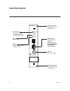
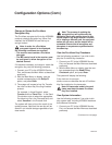
HCS6300
RF OUT
ETHERNET
Slot 1
Slot 12
Slot 5
CONTROLLER
Slot
Slot 6
Slot 7
Slot 8 Slot 9
Slot 10 Slot 11
Slot 2
Slots
3 & 4
SERVICE
PORT
RESET
STATUS
Note: All cards used in the card frame
must be inserted and removed by
qualified service personnel only.
Note: Use extreme care when handling an
HCS6600 card. Always observe proper
precautions with respect to static electric-
ity and mechanical shock. When not installed
in a card frame, return the HCS6600 card to the
anti-static bag in which it was shipped.
Note: The CodePlus series products are
NOT designed to be hot-swappable!!!
Power must be removed to the card
frame before any CodePlus transcoder cards
are inserted or removed.
Note: The card slots in the card frame
are NOT all identical!!! An HCS6600 card
can only be installed in Slots 1 to 6 and
7 to 12. The CONTROLLER slot between Slots
6 and 7 is dedicated for optional feature cards
and is not compatible with HCS6600 cards.
Note: When installing cards, remove
blank cover plates and insert new cards
as applicable. For ports that will not be
used, leave the blank cover plates in place
for proper ventilation and FCC and safety
agency compliance.
CONTROLLER Slot
The card in this slot may vary
depending on system features.
1. Unpack the HCS6600 unit(s) and all accessories.
Accessories provided: IEEE-1394 Cable
(Length = 1 meter)
2. Select the slot(s) in the card frame in which to
install the HCS6600. Note: All cards must be
used in an LG-approved card frame for this
product.
3. Remove the AC power cord for the card frame
from the power outlet.
4. Remove the blank cover plate from each slot
into which a card is to be inserted.
5. Without using force, slide each new card into
its designated slot, and ensure that it is fully
inserted.
6. Engage and tighten the top and bottom
thumbscrews securely. Note that the thumb-
screws should only be finger tight; overtighten-
ing may damage the assembly.
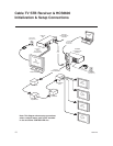
7. Refer to the diagram on page 10 for cable
connections, and complete the system instal-
lation and test procedure on page 11.