Chapter 6. PROGRAMMING
10 - 8
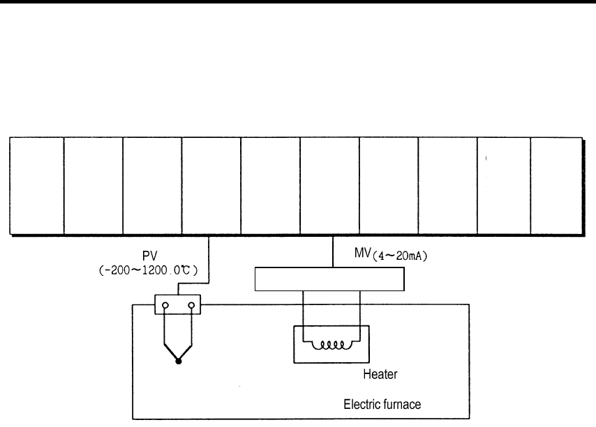
6.2.3 A Program for Control Using a Thermocouple
(with Applying the TC Input Module, PID Control Module and D/A Conversion Module)
1) System Configuration
2) Initial Settings
(1) TC input module
A) Specifying used channel : channel 0
B) Specifying TC type: K type
(2) PID control module
A) Specifying used loop : loop 0
B) Specifying forward/reverse action: forward action
C) Specifying auto/manual processing : auto processing
D) Setting SV: 200°C (4571 as digital value)
E) Setting M_MV (Used when errors occur) : 4500
F) Setting P : 3000
G) Setting I : 100
H) Setting D : 100
I) Auto processing is changed to manual processing when errors occur.
(3) D/A conversion module
A) Specifying used channel: channel 0
B) Specifying input data type: -192 ~ 16191
C) The output when no channel is used or the CPU module is in the stop state : The median value of the output
range.
3) Descriptions of the Program
1) The temperature of the electric furnace is converted into a digital value through the channel 0 of the TC input module,
and the digital value stored at address 18 is used as PV of the PID control module.
2) The MV of the PID control module is used as input digital data of the channel 0 of the D/A conversion module.
3) If an error occurs by the K type TC or the compensation wire which are connected to the TC input module (In the
channel 0, it is indicated at address 19.), then the PID control module changes auto processing into manual processing.
Power conversion device
TC (K type)
SV
( 200.0°C)
K7S-
122S
K7F-
TC4A
K7S-
30AS
K7X-
210S
K7S-
132S
K7Y-
201S
K7F-
PIDA
K7F-
DI4A
Ch. 0 Loop 0
Ch. 0
K7Y-
201S


