


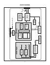
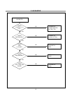

DESCRIPTION OF BLOCK DIAGRAM
- 9 -
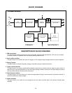
1. Input signal part.
There is one input which is analog.
It comes from 15 pin D-Sub connector.
2. Pre-amp/ ADC / PLL / Video Controller.
This part amplifies the level of video signal from the analog video signal to the digital video signal using a pixel
clock.
The pixel clock for each mode is generated by the PLL.
The range of the pixel clock is from 25MHz to 135.0MHz.
The Scaler gets the video signal converted analog to digital, interpolates input to 1280 X 1024 resolution signal
and outputs 8-bit R, G, B signal to LCD module.
Especially pre-amp / ADC / Video controller are merged to one chip ‘gm5020’ by Genesis.
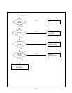
3. Power Part.
This circuit is working of 90~260VAC(50/60Hz). The operation procedure is as follows:
1) AC Input voltage is rectified and smoothed by the bridge diodes(BD901) and the capacitor(C905).
2) The Rectified voltage(DC) is applied to the primary coil of the transformer(T901).
3) The control IC(IC901) generates switching pulse to turn on and turn off the primary coil of the
transformer(T901).
4) Depending on turn ratio of the transformer, the secondary voltages appear at the secondary coils of the
transformer(T901).
5) These secondary voltages(12V,5V) are rectified by each diodes(D903,D906) and operates other
circuit.(Inverter,Scaler…etc)
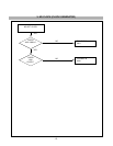
4. MICOM Part.
This part consists of EEPROM IC which stores control data, Reset IC and the Micom.
The Micom distinguishes polarity and frequency of the H/V sync are supplied from signal cable.
The controlled data of each modes is stored in EEPROM.
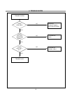
5. Inverter
The inverter converts from DC12V to AC 700V and operate back-light lamp of module.