


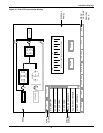
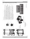
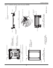
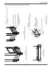
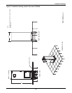
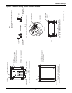
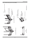
Installation Drawings
44
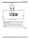
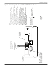
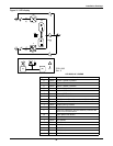
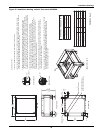
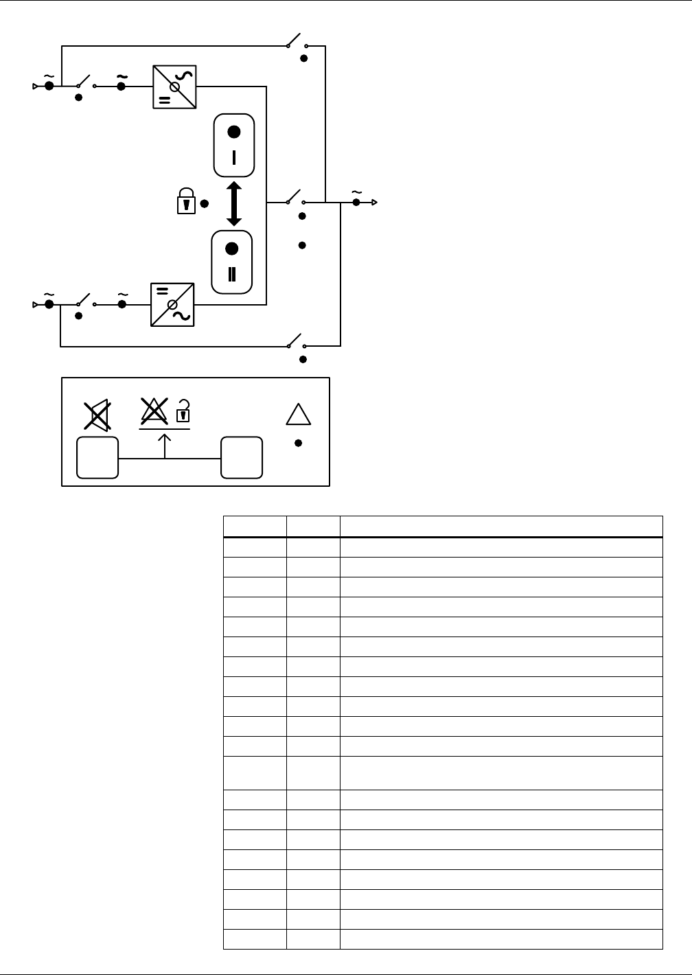
Figure 31 LED display
4
3
3A
(B)
2
(D)
(F)
5
(J)
(H)
(E)
1
(C)
1
(A)
(K) (M)
!
(N)
PS211002
Rev. 0
2
(L)
(G)
Symbol LED Description
A Green Source 1 Power is Present
B Green Source 2 Power is Present
C Green Source 1 Within Tolerance
D Green Source 2 Within Tolerance
E Green Source 1 SCRs is On
F Green Source 2 SCRs is On
G Yellow Source Transfer Inhibited
H Green Push Button to Select Source 1 as the Preferred Source
I Green Push Button to Select Source 2 as the Preferred Source
J Green Output Power is Present
K Alarm Silence Button
L
Symbol to Indicate the K and M Must Be pushed at the
Same Time to Reset Alarm
M Alarm Reset Push Button
N Red Alarm Present
1 Green CB1 Closed
2 Green CB2 Closed
3 Green CB3 Closed
3A Green CB3A Closed
4 Yellow CB4 Closed
5 Yellow CB5 Closed
LED DISPLAY LEGEND