Maintenance 41
Adding a Helios Rectifier 100/48
1. Remove the rectifier blank panel and store it for future use.
Note:
Should a rectifier be removed at any time, re-install the blank panel to meet the
regulatory requirements.
2. Verify that the AC, DC and signalling cabling for the rectifier shelf has been previously
installed and verified.
3. Ensure that the AC and DC circuit breakers on the front panel of the rectifier are in the OFF
position.
4. Carefully slide the rectifier into position, making sure that it is fully inserted.
5. Install the left and right side clamping brackets supplied with the rectifier to secure it into
position.
6. Operate the AC circuit breaker of the new rectifier to the “ON” position.
7. With the DC breaker in the “OFF” position, adjust the float, equalize and high voltage
shutdown voltage levels as required. Refer to the appropriate rectifier user manual (see
6.0 -
Reference Documents).
8. Install the corresponding sense fuse (RC) on the front of the controller.
9. Ensure that the FLS/FS switch on the rectifier is set to the same position as that of the other
rectifiers in the power system.
10. Operate the DC circuit breaker of the rectifier to the “ON” position.
11. Verify that the rectifier is sharing the load by observing its ammeter. It should display
approximately the same value as the ammeters on the other rectifiers. If not, adjust its float
and equalize voltage levels as described in the appropriate rectifier user manual (see
6.0 -
Reference Documents).
Adding a Helios Rectifier 200I/48 or 200E/48
1. Ensure that the AC and DC circuit breakers on the front panel of the rectifier are in the OFF
position.
2. Use a manual lift (or at least two people) to lift the rectifier to its position, rest it on the angle
guides, and slide it into the cabinet.
3. Align the mounting holes of the rectifier with those of the cabinet uprights and secure the
rectifier in place using the eight mounting screws provided.
Note:
A star washer must be used on one of the mounting screws.
4. Bring the connectorized AC cord up (top fed) or down (bottom fed) the cabinet and secure as
required.
5. Install the required circuit breaker at the AC service panel.
6. Ensure that the circuit breaker installed per
Step 5
is locked in the open (OFF) position.
7. Determine the length of cable (or individual wires in conduit) required to bring the AC supply
from the AC service panel to the rectifier cabinet.
8. Cut the cable (or wires) to the required lengths then run and secure between the AC service
panel and the rectifier cabinet.
9. Strip the sheeting and insulation material away from the ends of the wires to expose the AC
leads
10. For a Helios Rectifier 200E/48 without an AC cord, remove the AC protective cover at the rear
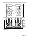
of the rectifier and connect the AC leads inside the rectifier as shown in
Figure 32,
then
reinstall the AC protective cover.
For a Helios Rectifier 200E/48 or a Helios Rectifier 200I/48 equipped with an AC cord, first
connect the associated female receptacle supplied with the rectifier to the cable (or wires)
incoming from the AC service panel (refer to
Figure 33).
Then, plug the male connector at the
end of the rectifier AC cord into the female receptacle.
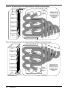
For a Helios Rectifier 200E/48 equipped with an AC cord, feed the cables through the appro-
priate strain relief connector at the top (top fed) or bottom (bottom fed) of the rectifier AC
junction box inside the cabinet (refer to
Figure 34).
Use a flat blade screwdriver to tighten
the strain relief connector, then connect the wires to the appropriate terminals inside the
junction box as shown in
Figure 34.
Use plastic cable ties to secure the wires at the tie down
points (one for each rectifier position) inside the junction box. Plug the male connector at the


