


13
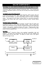
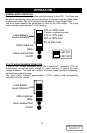
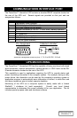
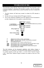
COMMUNICATIONS INTERFACE PORT
The PowerSure™ Interactive UPS contains a standard DB-9F recepticle located on
the rear of the UPS unit. Several signals are provided on this port and are
assigned as follows:
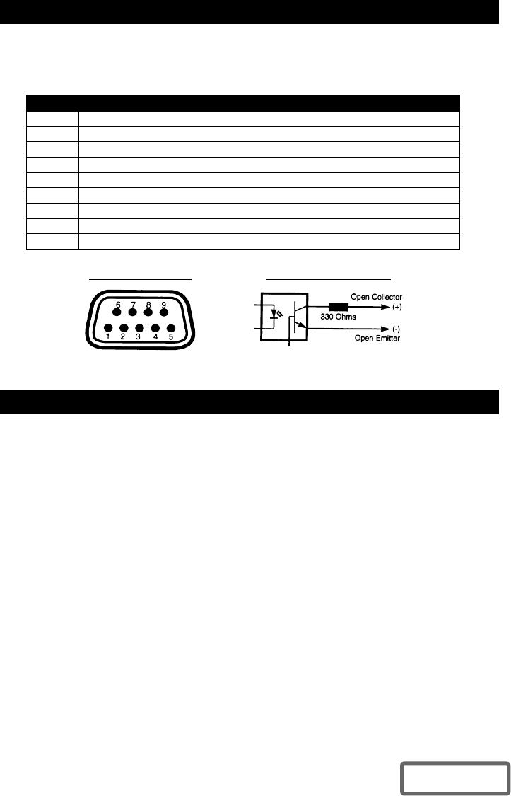
PIN ASSIGNMENT DESCRIPTION
1 Low Battery (open collector)
2 UPS TxD (typical RS-232 levels)
3 UPS RxD (typical RS-232 levels)
4 Remote Shutdown (5-12V DC, 1.0 mA. max.); battery operation
5 Common
6 No connection
7 Low Battery (open emitter)
8 Utility Fail (open emitter)
9 Utility Fail (open collector)
*Maximum voltage and current on pins 1, 7, 8, 9 is 80V DC; 10.0 mA.
UPS MONITORING
The PowerSure™ Interactive UPS has the capability of being monitored with stand
alone computers, network workstations, network servers, or UNIX hosts via the DB-
9 female connector located on the rear of the UPS.
This capability is used in applications requiring the UPS to provide status and
power monitoring information to the computer system. For example, during a utility
power failure, the information can be used by the computer’s operating system or
application program to automatically save information in buffers, to close files, and
shut down operations prior to battery capacity depletion.
Monitoring of the UPS via a computer system is easily made with a Liebert
SiteNet® 1 shutdown kit (sold separately). Consult your local Liebert
representative to determine the correct software kit for your application. The kit
includes special purpose cable and shutdown software.
Collector to Emitter*Pin Assignment
DISCONTINUED
PRODUCT