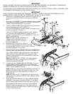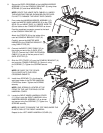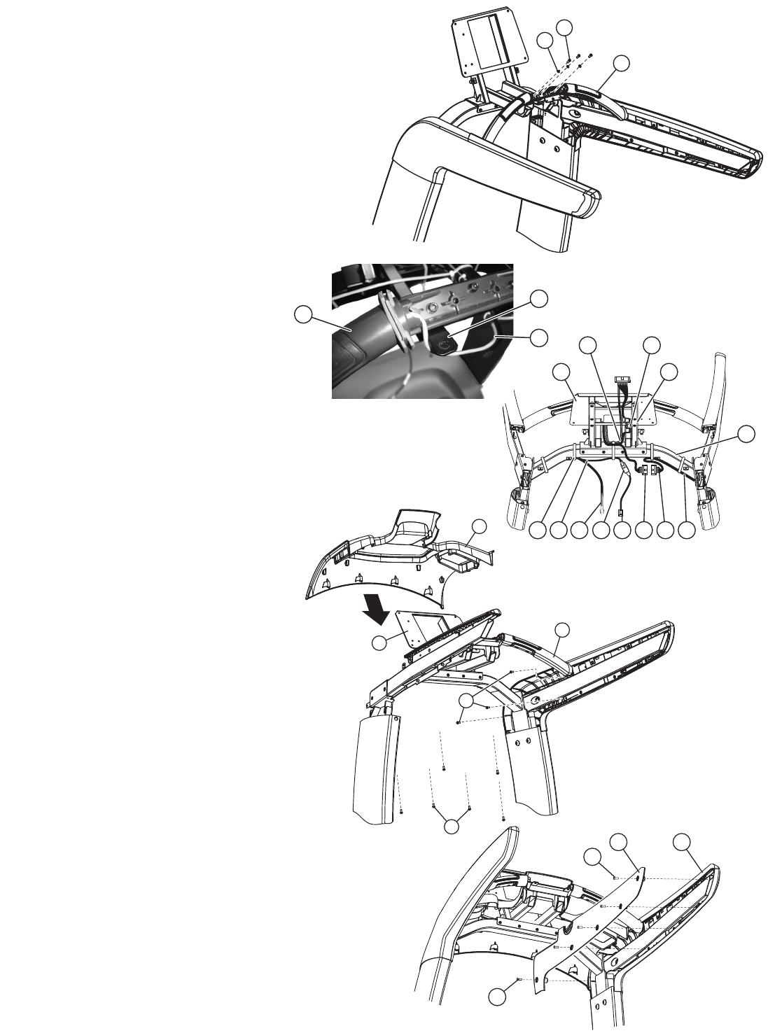
8. Secure the ERGO CROSSBAR of the HANDRAIL/BRIDGE
ASSEMBLY (5) to the CONSOLE BRACKET (6) using three
SCREWS (31) and three WASHERS (8).
NOTE: ROUTE THE HEART RATE CABLES (L) UNDER
THE MOUNTING TABS AS SHOWN BELOW. BE CARE-
FUL NOT TO DAMAGE THE HEART RATE CABLES.
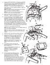
9. From under the HANDRAIL/BRIDGE ASSEMBLY (5),
install the MASTER WIRE HARNESS (9) to the CON-
SOLE (D) and HEART RATE (L) CABLES. WIRE-TIE
(M) the cables to the CONSOLE BRIDGE as shown.
Feed the combined connector upward to the back
of the CONSOLE BRACKET (6).
Attach the FERRITE (W) to the inside of the
user left CONSOLE BRACKET POST (X).
Carefully secure the MASTER WIRE
HARNESS to the CONSOLE BRACKET
using CABLE TIES (32)
10. Connect the BASE C-SAFE CABLE (G) to
the single port end of the C-SAFE SPLIT-
TER (Z). Connect the C-SAFE EXTENSION
CABLE (Y) to one of the two ports of the C-
SAFE SPLITTER (Z).
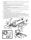
11. Slide the TOP COVER (10) over the CONSOLE BRACKET (6)
and onto the CONSOLE BRIDGE (5). Secure it using
six SCREWS (7). Tighten the SCREWS secure-
ly.
NOTE: BE SURE THE TOP COVER
FULLY SEATS INTO THE ERGO
CROSSBAR GASKETS.
12. Install three SCREWS (7) in the three for-
ward-most holes of the OUTER HANDRAIL
COVERS as shown. Tighten the SCREWS
securely.
NOTE: ONE SCREW IS LOCATED AT THE
FRONT OF THE UNIT FOR EACH OUTER
HANDRAIL COVER.
13. Locate the RIGHT INNER HANDRAIL COVER
(11). Align it onto the RIGHT HANDRAIL of the
HANDRAIL/BRIDGE ASSEMBLY (5) as shown
and secure using five SCREWS (7). Tighten the
SCREWS securely.
NOTE: BE SURE TO ENGAGE THE TOP TABS UNDER THE
PLASTIC RAIL OF THE RIGHT HANDRAIL.
Repeat for the LEFT INNER HANDRAIL COVER (12).
31
8
5
6
7
10
5
7
7
11 5
7
D
X
HM E
5
L W
9Z
6
YG
L
5
N


