


23
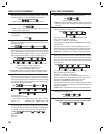
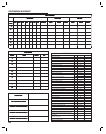
Relay #2 Alternate Options Default: Access Relay
Relay #2 can be used for functions other than triggering a gate operator or
door strike. Relay #2 can be programmed to shunt alarm contacts during
Relay #1 activation or perform up to fi ve Alarm Functions. Two PPN numbers
are used to program the Relay #2 options.
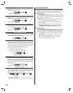
Press:
Role
Role: 0 = Access Relay
1 = Alarm Shunt (Follows Relay #1 activation, used to shunt
external alarm contacts with Relay #2’s contacts)
2 = Obstacle Detector
3 = Activate during one or more of the fi ve Alarm
Functions programmed below
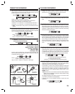
✦ NOTE: More than one alarm function can be enabled at a time. Up to fi ve
digits can be entered for “Activate”.
Press:
Activate
Activate: 0 = No alarm function (default)
1 = On forced entry (activates when SENSE #1 input opens
without Relay #1 activation)
2 = On door/gate ajar (activates when SENSE #1 input stays
open for longer than one minute after Relay #1 activation)
3 = On main keypad lockout (activates when the main keypad
is in “lockout” from too many incorrect code attempts)
4 = On remote keypad lockout (activates when the remote
keypad is in “lockout” from too many incorrect code
attempts)
5 = On driveway sensor (activates when SENSE #2 input closes)
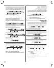
Model MGT Gate Edge Transmitter Setup
Linear’s Model MGT Gate Edge Transmitter can be used with the RE-1
for obstacle detection. When the gate edge sensor triggers the MGT
transmitter, the RE-1 can be programmed to activate Relay #2 which would
in turn, activate the obstacle input of the gate operator.
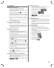
Press:
Obstacle
Facility
ID
Obstacle: 0 = No MGT obstacle transmitter (default)
1 = MGT obstacle transmitter used
Facility: Facility code 0-15 of MGT transmitter
ID = 5-digit ID number of transmitter
✦ NOTE: The Facility and ID entries are not required if Obstacle is set to
“0”.
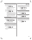
Remote Keypad Address Default: 3
If a Linear Model AM-KP is used as a remote keypad the ADDRESS switch
in the remote keypad needs to match the “address” setting in the RE-1. For
most installations, simply set the remote keypad’s ADDRESS switch to “3”
to match the RE-1 default setting. If required, use the following programming
PPN to change the address number.
Press:
Address
Address: 0 = Remote keypad disabled
1-6 = Keypad address 1-6
✦ NOTE: After changing the keypad address, restart the system using the
RESTART button.
Sense Input Alternate Function Defaults:
SENSE #1 = SENSE
SENSE #2 = SENSE
Each of the two SENSE inputs can be independently programmed to act
as INHIBIT inputs. As an INHIBIT input, as long as the input is grounded,
access can not be granted for that input’s relay (1 or 2). A typical application
would be connection of an external timer or service switch to temporarily
prevent visitors from activating the access device.
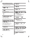
Press:
Input Type
Input: 1 = SENSE #1
2 = SENSE #2
Type: 0 = Input will perform as SENSE
1 = Input will perform as INHIBIT
Keypad Lockout Count Default: 5 Tries
The Keypad Lockout Count sets the number of incorrect code entry attempts
required to place the keypad in “lockout” for a one minute period. During
“lockout” the keypad will not accept any code entries. The Keypad Lockout
Count effects both the main and remote keypads.
Press:
Count
Count = 2-7 Incorrect entries
Anti-passback Time Default: Off
The Anti-passback feature prevents the same entry code or transmitter
from being used to gain access more than once during the set time.
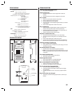
Press:
Time
Time: 0 = No anti-passback
1-4 = Anti-passback time (in minutes)
Modem Ring Detect On/Off Default: On
The RE-1’s built-in modem monitors the telephone line for telephone rings.
When the Modem Ring Detect is enabled, the modem will answer the
telephone if two consecutive telephone calls occur within 30 seconds. The
Modem Ring Detect can be disabled, this will also disable any computer
based programming of the RE-1.
Press:
Detect
Detect: 0 = Ring detect OFF
1 = Ring detect ON