


Chapter 1
Product Overview
1
Gigabit 8-Port Workgroup Switch
Chapter 1:
Product Overview
The Gigabit 8-Port Workgroup Switch delivers non-blocking,
wire speed switching for your 10, 100, and 1000 Mbps
network clients, so all workstations will perform at their
maximum speeds.
Gigabit speeds are perfect for graphics, multimedia, and
other applications that have to quickly move large files
across the network. Connect your Gigabit-equipped
workstations to the Switch’s 10/100/1000 ports, so they
will have full-duplex, dedicated bandwidth of up to
1000 Mbps, while the other clients continue to run at their
current 10/100 Mbps speeds.
Use the instructions in this User Guide to help you install
the Switch.
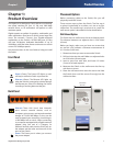
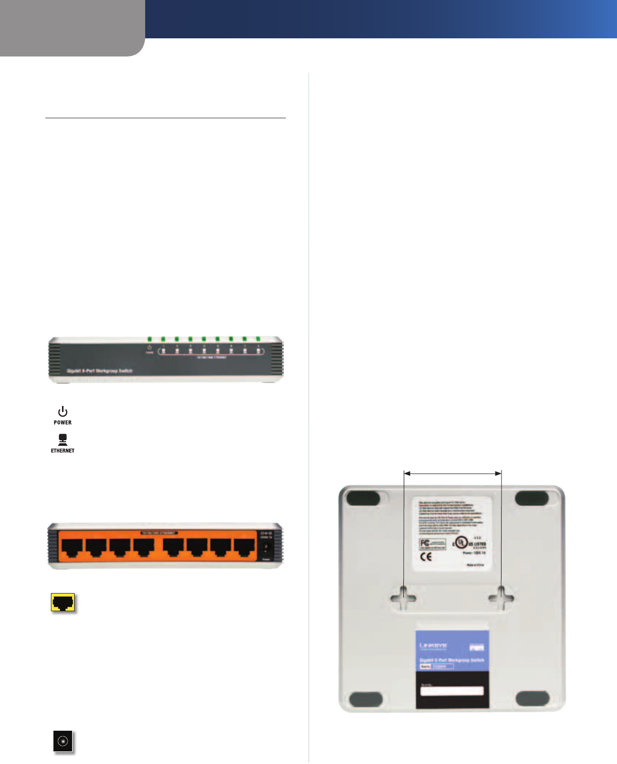
Front Panel
Power (Green) The Power LED lights up and
will stay on while the Switch is powered on.
Ethernet (Green)
The Ethernet LED lights up
when the Switch is connected to a device through
the Ethernet port. If the LED is flashing, the Switch
is sending or receiving data over that port.
Back Panel
Ethernet These LAN (Local Area Network)
ports connect network devices, such as
computers, print servers, and network attached
storage at 10/100/1000 Mbps. Or, they can be
used to expand your network by connecting to
a 1000 Mbps hub or switch. When connecting
to a computer equipped with a Gigabit network
adapter, plug one end of a Category 5e
Ethernet network cable into the RJ-45 port on
the adapter and the other end into one of the
ports on the Switch.
Power The Power port is where you connect
the power adapter.
Placement Options
Before connecting cables to the Switch, first you will
physically install the Switch.
There are two ways to place the Switch. The first way is
to place it horizontally on a surface, so it sits on its four
rubber feet. The second way is to mount it on a wall. The
wall-mount option is described in further detail below.
Wall-Mount Option
The Switch has two wall-mount slots on its bottom panel.
The distance between two adjacent slots is 2.36 inches
(60 mm).
Before you begin, make sure you have two screws that
are size #4—this indicates a diameter measurement of
0.112 inches (2.845 mm).
1. Determine where you want to mount the Switch.
2. Drill two holes into the wall. Make sure adjacent holes
are 2.36 inches (60 mm) apart.
3. Insert a screw into each hole, and leave 0.2 inches
(5 mm) of its head exposed.
4. Maneuver the Switch so the wall-mount slots line up
with the two screws.
5. Place the wall-mount slots over the screws and slide
the Switch down until the screws fit snugly into the
wall-mount slots.
2.36 inches
(60 mm)