


5
Chapter 3: Connecting the 10/100
Switch
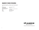
Planning Your Network Layout
This chapter will explain how to connect network devices to the Switch. For an
example of a typical network configuration, see the application diagram shown
in Figure 3-1.
When you connect your network devices, make sure you don’t exceed the max-
imum cabling distances, which are listed in the following table:
Maximum Cabling Distances
*A hub refers to any type of 100Mbps hub, including regular hubs and stackable hubs. A 10Mbps hub
connected to another 10Mbps hub can span up to 100 meters (328 feet).
4
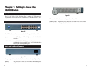
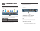
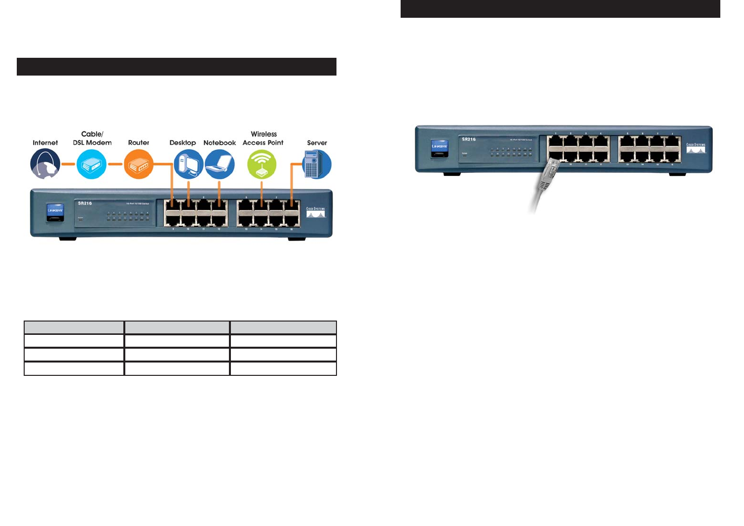
To connect network devices to the Switch, follow these instructions. (The 16-
Port 10/100 Switch is shown in Figure 3-2.)
1. Make sure all the devices you will connect to the Switch are powered off.
2. Connect a Category 5 Ethernet network cable to one of the numbered ports
on the Switch.
3. Connect the other end to a PC or other network device.
4. Repeat steps 2 and 3 to connect additional devices.
5. Connect the supplied power cord to the power port on the Switch’s back
panel.
6. Plug the other end of the power cord into an electrical outlet.
7. Power on the devices connected to the Switch. Each active port’s corre-
sponding LED will light up on the Switch.
Proceed to the following section, “Placement Options.”
Connecting Network Devices
Figure 3-2
From
Switch
Hub
Switch or Hub
Switch or Hub*
Hub
Computer
Maximum Distance
100 meters (328 feet) 1
5 meters (16.4 feet) 1
100 meters (328 feet) 1
To
Overview
Figure 3-1