7
Appendix A: Glossary
10BaseT - An Ethernet standard that uses twisted wire pairs.
100BaseTX - IEEE physical layer specification for 100 Mbps over two pairs of
Category 5 UTP or STP wire.
Auto MDI/MDI-X - On a network hub or switch, an auto MDI/MDI-X port
automatically senses if it needs to act as a MDI or MDI-X port. The auto-
MDI/MDI-X capability eliminates the need for crossover cables.
Auto-negotiate - To automatically determine the correct settings. The term is
often used with communications and networking. For example, Ethernet
10/100 cards, hubs and switches can determine the highest speed of the node
they are connected to and adjust their transmission rate accordingly.
CAT 5 - ANSI/EIA (American National Standards Institute/Electronic
Industries Association) Standard 568 is one of several standards that specify
“categories” (the singular is commonly referred to as “CAT”) of twisted pair
cabling systems (wires, junctions, and connectors) in terms of the data rates
that they can sustain. CAT 5 cable has a maximum throughput of 100 Mbps and
is usually utilized for 100BaseTX networks.
CAT 5e - The additional cabling performance parameters of return loss and far-
end crosstalk (FEXT) specified for 1000BASE-T and not specified for
10BASE-T and 100BASE-TX are related to differences in the signaling imple-
mentation. 10BASE-T and 100BASE-TX signaling is unidirectional-signals
are transmitted in one direction on a single wire pair. In contrast, Gigabit
Ethernet is bi-directional-signals are transmitted simultaneously in both direc-
tions on the same wire pair; that is, both the transmit and receive pair occupy
the same wire pair.
Ethernet - IEEE standard network protocol that specifies how data is placed
on and retrieved from a common transmission medium. Has a transfer rate of
10 Mbps. Forms the underlying transport vehicle used by several upper-level
protocols, including TCP/IP and XNS.
Fast Ethernet - A 100 Mbps technology based on the 10Base-T Ethernet
CSMA/CD network access method.
6
There are three ways to physically install the Switch:
• set the Switch on its four rubber feet
• mount the Switch in a standard rack (1U high)
• hang the Switch on a wall using its wall-mount slots.
To rack mount the Switch, follow these instructions:
1. The Switch has four mounting holes on each side. Screw an included mount-
ing bracket into each side.
2. Lift the Switch into the rack, and secure the brackets with additional screws
(not included).
To hang the Switch on a wall, follow these instructions:
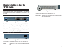
1. The wall-mount slots are two
crisscross slots on the Switch’s
bottom panel (see Figure 3-3).
The distance between the two
slots is 95 mm. Attach two
screws to the wall, so that the
Switch’s wall-mount slots line
up with the two screws.
2. Maneuver the Switch so the screws are inserted into the two slots.
Congratulations!
The installation of the 10/100 Switch is complete.
Placement Options
Figure 3-3


