


Chapter 5
Advanced Configuration
48
WebView Switches
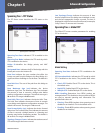
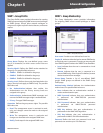
Spanning Tree > MSTP Instance Settings
MSTP operation maps VLANs into STP instances. Packets
assigned to various VLANs are transmitted along different
paths within Multiple Spanning Trees Regions (MST
Regions). Regions are one or more Multiple Spanning
Tree bridges by which frames can be transmitted. In
configuring MST, the MST region to which the device
belongs is defined. A configuration consists of the name,
revision, and region to which the device belongs.
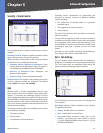
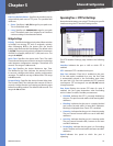
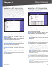
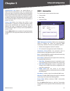
Spanning Tree > MSTP Instance Settings
Network Administrators can define MSTP Instances
settings using the MSTP Instance Settings screen.
Instance ID Defines the VLAN group to which the
interface is assigned.
Included VLAN Maps the selected VLAN to the selected
instance. Each VLAN belongs to one instance.
Bridge Priority Specifies the selected spanning tree
instance device priority. The field range is 0–61,440.
Designated Root Bridge ID Indicates the ID of the bridge
with the lowest path cost to the instance ID.
Root Port Indicates the selected instance’s root port.
Root Path Cost Indicates the selected instance’s path
cost.
Bridge ID Indicates the bridge ID of the selected
instance.
Remaining Hops Indicates the number of hops remaining
to the next destination.
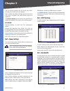
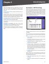
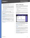
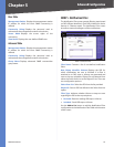
Spanning Tree > MSTP Interface Settings
Network Administrators can assign MSTP Interface settings
using the MSTP Interface Settings screen.
Spanning Tree > MSTP Interface Settings
The MSTP Interface Settings screen contains the following
fields:
Instance ID Lists the MSTP instances configured on the
device. Possible field range is 0–15.
Interface Displays the interface for which the MSTP
settings are displayed. The possible field values are:
Port • Specifies the port for which the MSTP settings
are displayed.
LAG • Specifies the LAG for which the MSTP settings
are displayed.
Port State Indicates whether the port is enabled for the
specific instance.
Type Indicates if the port is a point-to-point port, or a
port connected to a hub. The possible field values are:
Boundary Port • Indicates the port is a boundary port.
A Boundary port attaches MST bridges to LAN in an
outlying region. If the port is a boundary port, it also
indicates whether the device on the other side of the
link is working in RSTP or STP mode.
Master Port • Indicates the port is a master port. A
Master port provides connectivity from a MSTP region
to the outlying CIST root.
Internal • Indicates the port is an internal port.
Role Indicates the port role assigned by the STP algorithm
in order to provide to STP paths. The possible field values
are:
Root • Provides the lowest cost path to forward packets
to root device.
Designated • Indicates the port or LAG via which the
designated device is attached to the LAN.