


9
5 Cascade Screen
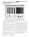
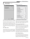
Figure 5-1 Cascade Screen
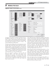
The Cascade Screen provides the status of the cascade system.
The PC must be connected to the Leader (address 0-1)
appliance. Click on the Cascade button along the top of the
Main Screen window (FIG. 1-1).
The Cascade System area shows the power demand and
setpoint, the boiler pump status, the boiler status, and the
priority of each controller in the cascade. If a system supply
sensor is connected to the Leader controller, the cascade
control will send a fixed setpoint of 185°F (85°C) and a power
(% modulation) command to all the heaters as required to
maintain the controlled temperature at the setpoint. If a
system supply sensor is not connected (NOT recommended),
the Leader will send the space heating setpoint to all of the
boilers in the cascade and each controller will fire as required
to hold their outlet sensors to this setpoint.
The Priority column indicates the order in which the
controllers will fire to meet the load. This order changes every
hour during the first day of operation, and every 24 hours
thereafter.
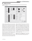
The Sensors area displays the system supply temperature, and
space heating setpoint (see FIG. 5-1).
Beneath this area is a check box indicating if Night Setback is
active. Beneath that is a check box indicating if the
temperature regulation is being held constant, and if the
Ramp Delay feature is active. The Freeze P1 regulation box is
checked when the next controller can be started up, but is held
off by one of the timers.
The Status area displays several important parameters. The
Cascade Pump gives the status of the system pump output, and
the type of heat demand (Space Heating or HW). The Cascade
power shows the power target for the cascade, and the total
power available. This target power may not be the same as the
total power shown in the Cascade System area, due to the
various time delays described below. The Cascade Max and
Cascade Min values show the maximum and minimum fan
speed percentages available in all of the heaters. The Off Timer
and On Timer are used to force each controller to have a
minimum off and on time, to prevent short cycling. The Block
Switch on timer is started whenever a controller is commanded
to start, and the next controller is prevented from starting until
this timer times out. This allows time for the system supply
sensor to read the temperature change resulting from firing the
last controller, before starting the next.
By clicking on the Options button, a log file can be defined, and
logging can be started and stopped in the same way as with the
Status and Graphics Screens previously described. A bitmap of
the current screen can also be saved if desired.
PC Program Instructions