


1. Connect the 40 pin interface cable to the IDE Sub output on the External IDE Bay Unit. Connect the
other end of this cable to the IDE Sub input on the back of the DVR or DVR combo unit
2. Follow the procedure in the DVR or DVR Combo owner’s manual for installing the HDD unit.
Important Note: If you are using your own HDD, please set the jumper to SLAVE. Refer to the
instructions included with your HDD for more information. Depending on the
model purchased, an HDD may or may not be included.
3. Plug in the 12V DC power adapter into an AC outlet, and turn the power switch ON
4. When you start-up your DVR or DVR Combo the system will automatically detect the MASTER drive
only. For the system to detect both the MASTER and SLAVE, you will need to go into the MAIN MENU
CONTROL and select the HDD/REC SET and set the parameters to activate the HDD slave.
Note: These steps are outlined in the MAIN MENU CONTROL section of the DVR or DVR Combo’s
Owner’s Manual
When the MASTER HDD becomes FULL during recording, the SLAVE HDD becomes the active drive,
receiving the earliest recorded data from the MASTER HDD. Therefore, data is not lost, as it gets
transferred to the SLAVE HDD.
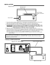
INSTALLATION:
Power Switch
12V DC Power
Adapter Connection
Back of Unit
AUDIO
SLAVE
OUT
4
VIDEO
MONITOR
OUT
IDE-SUB
USB
+ -
SENSOR INPUT SENSOR
OUTPUT
AC100-240V,50/60Hz
AC INPUT
POWER
MAIN S/W
CH4CH2
VIDEO INPUT
CH2 CH4
CH1 CH3
+ -
1 2 3
+ -
AUDIO INPUT
+ - + -
CH1 CH3
RS-232
40 pin Interface cable
Back of a 21” DVR Combo
Back of HDD Bay
TYPICAL CONFIGURATION:
IDE Sub Output
(40 pin)