


Physical Characteristics 2-25
Ver. 2.0 Copyright © 2002 by LSI Logic Corporation. All rights reserved.
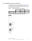
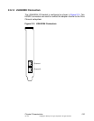
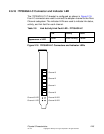
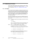
2.6.18 ITI7004G2-LC Connector and Indicator LED
The ITI7004G2-LC I/O bracket is configured as shown in Figure 2.18.
Four LC connectors are used to connect the adapter channel to the Fibre
Channel subsystem. The indicator LEDs are used to indicate link status,
activity, and link fault for each channel.
Figure 2.18 ITI7004G2-LC Connectors and Indicator LEDs
Table 2.9 Link Activity/Link Fault LED - ITI7004G2-LC
Link Activity Fault
Appearance of LED
Green Green Blinking Yellow
Channel 2 LED
Channel 0
Channel 0 LED
Channel 3 LED
Channel 1 LED
Channel 1
Channel 2
Channel 3