


2-12 Installing the LSI21003
Most PC cabinets are designed with a front panel LED. If you wish to
enable this feature, follow Step 4.
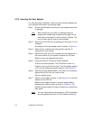
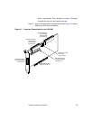
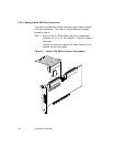
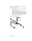
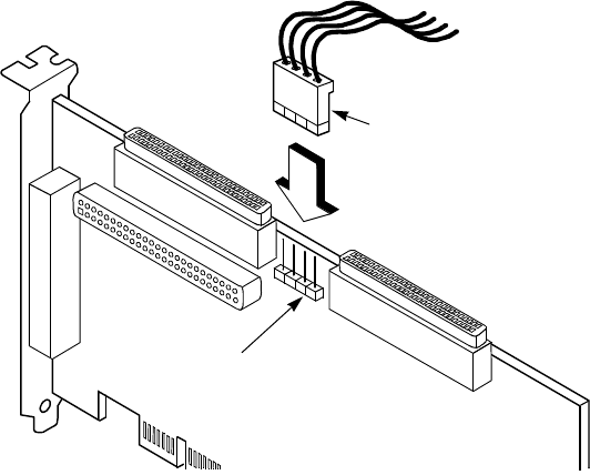
Step 4. Connect the LED cable to connector J6 on the host adapter, as
shown in Figure 2.8.
When properly connected, the front panel LED lights when
there is activity on the SCSI bus.
Connector J6 is not keyed. The orientation of the LED cable
should not matter as long as all four pins are connected. If the
LED does not light during SCSI bus activity from this host
adapter, you may have to rotate the LED cable connector 180
°
on J6. If your connector has only two wires, refer to Table 3.8
on page 3-12 for connector pinout information.
Figure 2.8 SCSI LED Connector
LED Cable
Connector
LED
Connector
J6