


3-12 Technical Specifications
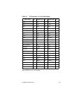
3.2.2.1 SCSI Activity LED Interface
The LED interface allows an LED harness to be connected to the board.
J6 is the connector for both channels. Table 3.8 lists the signals and pin
numbers for Connector J6.
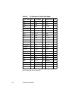
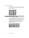
3.3 Subsystem and Subsystem Vendor ID
The Subsystem ID and System Vendor ID for the LSI21003 are provided
in Table 3.9. The EEPROM of the LSI21003 contains the ID numbers.
During system initialization, the ID numbers are loaded into the
Subsystem Vendor ID and Subsystem ID registers of the imbedded SCSI
controller, the LSI53C1010. For more information on the operation of the
Subsystem Vendor ID and Subsystem ID registers, refer to the
LSI53C1010-33 PCI to Dual Channel Ultra3 SCSI Multifunction
Controller Technical Manual.
Table 3.8 Connector J6 Signals
Signal Name Pin
A_LED+ 1
A_LED− 2
B_LED− 3
B_LED+ 4
Table 3.9 Subsystem and Subsystem Vendor ID
Subsystem ID Number
Subsystem Vendor ID 1000
Subsystem ID 1050