


MegaRAID PCI to Serial ATA Storage Adapters 3-3
Copyright © 2002–2006 by LSI Logic Corporation. All rights reserved.
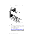
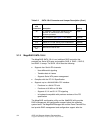
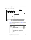
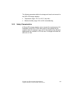
Figure 3.1 shows the layout of the SATA 150-6.
Figure 3.1 SATA 150-6 Board Layout
Tabl e 3.2 lists the connectors on the SATA 150-6.
J1 J2 J3
J4 J5 J6
J13
J14
J16
J17
J7 J8 J9 J10 J11 J12
J15
Port 0 Port 1 Port 2 Port 3 Port 4 Port 5
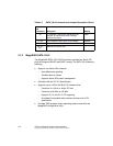
Table 3.2 SATA 150-6 Connector and Jumper Description
Jumpers
and
Connectors
Description Setting
J1 Reserved for internal use Do not
install a
jumper.
J2 Open - BIOS enabled; Installed - BIOS disabled Open
J3 Reserved for internal use –
J4 Write Pending connector. Provides a signal that
indicates when the on-board cache contains data
and a write from the cache to the hard drives is
pending.
–
J5 Serial I/O connector for Serial EPROM Open