


5
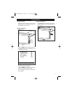
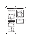
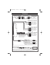
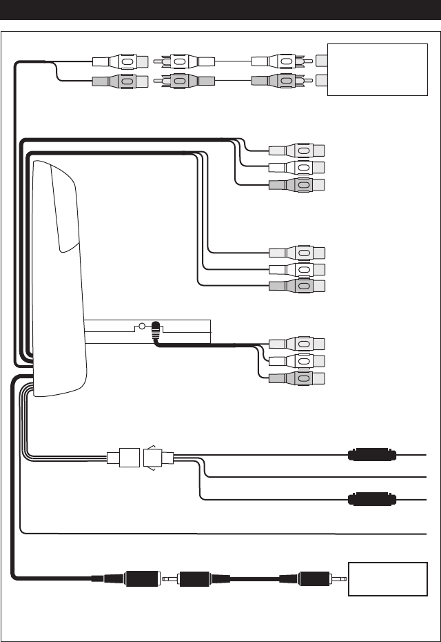
Wiring Diagram
Yellow (VIDEO IN)
White (L-AUDIO IN)
Red (R-AUDIO IN)
Audio/Video Input 2* (Female RCA)
Audio Output (Female RCA)
Remote Eye Connection
(Cable Supplied)
Black Wire - Ground
Red Wire - Ignition
Yellow Wire - Battery
White Wire - Negative Domelight Door Trigger
Yellow (VIDEO IN)
White (L-AUDIO IN)
Red (R-AUDIO IN)
Audio/Video Input 1 (Female RCA)
Yellow (VIDEO IN)
White (L-AUDIO IN)
Red (R-AUDIO IN)
Audio/Video Input 2* (Female RCA)
1 A
3 A
DVD PLAYER
(Not Supplied)
or
*Note: If external cable is used
for Audio/Video Input 2 the
internal Audio/Video Input 2
RCA’s will not function.
Male-to-Male Cable
(Not Supplied)
Optional FM Transmitter
(Model: MV-TX2)
or other
Transmitter Device
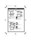
Note: When creating passage holes for the power wires, use grommets to eliminate any sharp edges
made during drilling. This will protect the wires from being nicked, causing a short circuit.
MV750-UM.qxp 6/15/07 11:44 AM Page 5