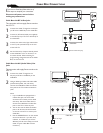
CABLE
IN
TO
TV
VIDEO
OUT
SVIDEO
L
R
AUDIO
OUT
3 4
OUTPUT
CH
Cable Box
Cable TV singal
1
2
AV Player with A/V connectors
1
CC
SOURCE
PIP
MENU
OK
2
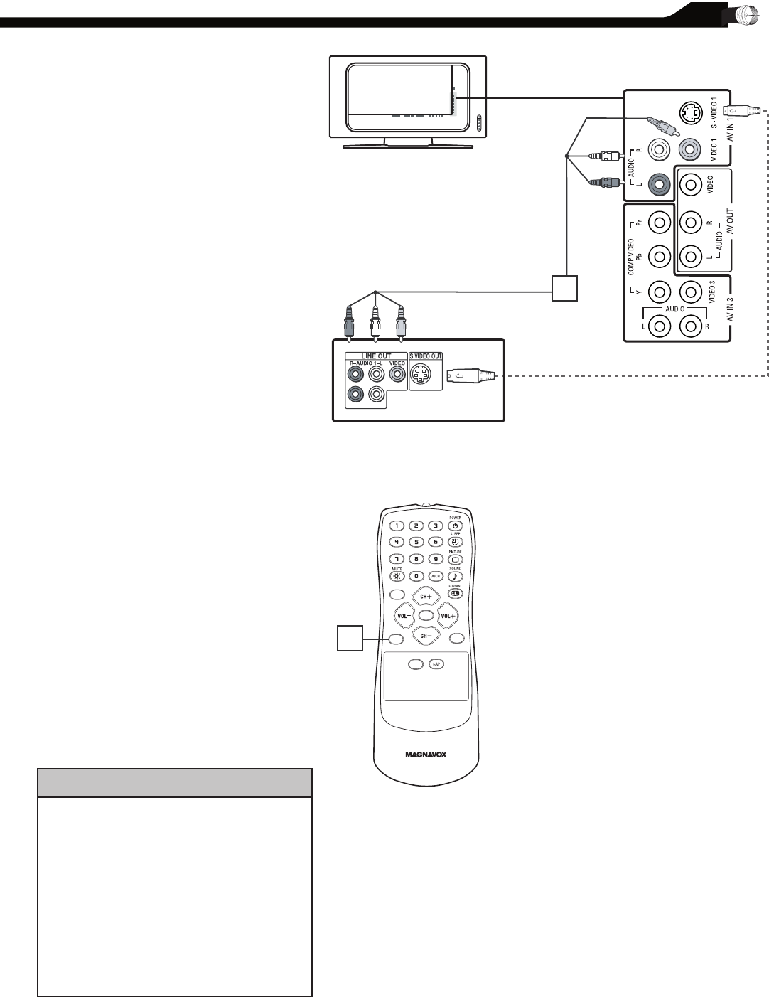
VCR, DVD PLAYER, OR OTHER DEVICES
WITH RCA CONNECTORS
T
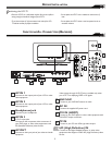
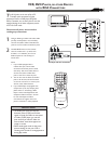
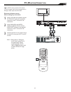
he AV IN jacks on the rear of the LCD
TV enable quick connections of other
equipment. Connect a DVD player, VCR Video
Game, Camcorder, etc., to these jacks. To view the
material playing on the other equipment, set the
LCD TV to its AV mode.
Disconnect all power sources before
making any connections.
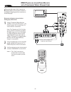
Using an RCA-type Video and Audio cable
(usually marked yellow, red, and white),
connect the VCR’s Video and Audio Out
jacks to the TV’s Video and Audio In jacks.
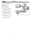
Use SOURCE button on the remote
control to select AV 1 (or AV2, AV3,
S-Video1, or S-Video2 if you use the
different jacks for this hookup) to
watch VCR.
Note:
1. If your VCR equipped with a
S-Video Out jack, uses S-Video
connection for better picture detail
and clarity. Use the S-Video cable to
connect the VCR’s S-Video Out
jacks to the TV’s S-Video In jacks.
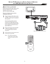
2. You can also use the Video and Audio
jacks in AV IN 2 and AV IN 3 located
on the rear of the TV to connect your
VCR or other Video Devices.
3. If your DVD Player is equipped with
Component (Y, Pb, Pr) Output Jacks,
please refer to “Connecting a DVD
Player or other Video Equipments with
Component Video Connectors” section
for use of Component Video
Connection for highest color and
picture resolution in video playback.
1
11
2
HELPFUL HINT
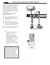
• The Audio jack of AV IN is shared
between Video (CVBS) and S-Video
signals. If Audio and Video is connected
to Video (CVBS) input, you can still
hear sound if you select S-Video via
Source select, even there appears no
image on screen.
• Select weak signal mode via the smart
picture settings in case your VCR is
showing a lot of noise or strange patterns
during play mode.


