


4
4. Cutting workpieces covered with oil can cause
the blade to come off unexpectedly. Wipe off all
excess oil from workpieces before cutting.
5. Never use the cutting oil as a cutting lubricant.
Use only Makita cutting wax.
6. Do not wear gloves during operation.
7. Hold the tool firmly with both hands.
8. Keep hands away from rotating parts.
9. When cutting metal, be cautious of hot flying
chips.
10. Do not leave the tool running unattended.
11. Do not touch the blade or workpiece immediately
after operation; they are extremely hot and could
burn your skin.
12. Hold tool by insulated gripping surfaces when
performing an operation where the cutting tool
may contact hidden wiring or its own cord. Con-
tact with a “live” wire will make exposed metal
parts of the tool “live” and shock the operator.
SAVE THESE INSTRUCTIONS
WARNING:
MISUSE or failure to follow the safety
rules stated in this instruction manual
may cause serious personal injury.
SYMBOLS
USD201-2
The followings show the symbols used for tool.
V............................volts
A ...........................amperes
Hz..........................hertz
..................alternating current
.......................no load speed
.......................Class II Construction
.../min....................revolutions or reciprocation per
minute
FUNCTIONAL DESCRIPTION
CAUTION:
• Always be sure that the tool is switched off and
unplugged before adjusting or checking function on
the tool.
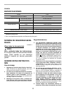
Switch action
CAUTION:
• Before plugging in the tool, always check to see
that the switch trigger actuates properly and returns
to the “OFF” position when released.
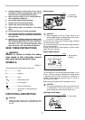
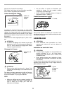
To start the tool, simply pull the switch trigger. Release
the switch trigger to stop.
For continuous operation, pull the switch trigger and then
push in the lock button.
To stop the tool from the locked position, pull the switch
trigger fully, then release it.
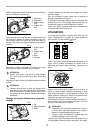
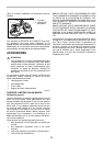
Speed adjusting dial
The tool speed can be infinitely adjusted between 1.0 m/
s and 1.7 m/s by turning the adjusting dial. Higher speed
is obtained when the dial is turned in the direction of
number 5; lower speed is obtained when it is turned in
the direction of number 1.
Select the proper speed for the workpiece to be cut.
CAUTION:
• The speed adjusting dial can be turned only as far
as 5 and back to 1. Do not force it past 5 or 1, or the
speed adjusting function may no longer work.
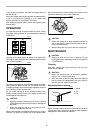
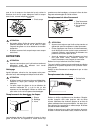
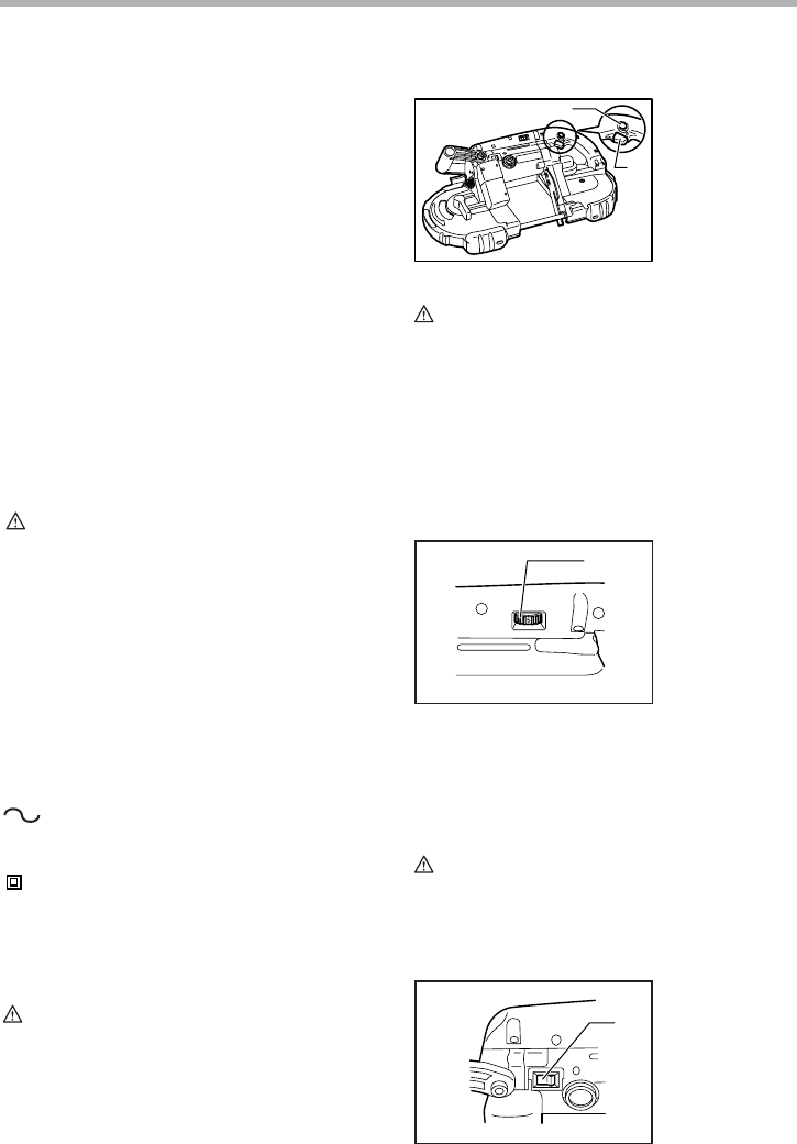
Lighting up the lamps
n
˚
1. Lock button
2. Switch trigger
1. Speed adjust-
ing dial
1. Lamp switch
1
2
006189
1
005896
1
005897