


38
P. ON DELAY (Power on delay)
Use this function to activate power-on delay.
Turn on the AUTO ID before the following operations.
Example: Setting “ON”
Perform Steps 1-2 of VIDEO WALL, then...
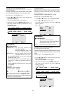
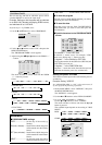
3. Use the ▲ and ▼ buttons to select “P. ON DELAY”.
4. Use the
ᮤ
and
ᮣ
buttons to select “ON”.
The mode switches as follows each time the
ᮤ
or
ᮣ
button is pressed:
OFF ↔ ON
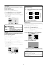
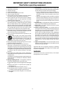
VIDEO WALL
EXIT
DIVIDER
POSITION
DISP. MODE
AUTO ID
IMAGE ADJUST
P. ON DELAY
PLE LINK
REPEAT TIMER
: 1
: SPLIT
: OFF
: ON
: OFF
: OFF
SEL.
RETURN
ADJ.
Information
Ⅵ P. ON DELAY settings
ON ...... Turns on the main power of each display after
a delay time.
OFF .... Turns on the main power of all displays at the
same time.
* Once this function has been set to “ON”, POWER ON/
OFF button on the remote control does not function
except for the No.1 monitor.
By pressing the POWER ON button on the remote
control the No.1 monitor will turn on and the others
will be turned on one by one automatically.
* From the second monitor onward, neither the POWER
button on the unit nor the POWER ON button on the
remote control does function. However, by pressing and
holding the POWER ON button for more than 3 seconds,
the monitor will be turned on.
PLE LINK
Use this function to set a uniform brightness for each
display.
Turn on the AUTO ID and set the DIVIDER (at 1, 4 or 9)
before the following operations.
Example: Setting “ON”
Perform Steps 1-2 of VIDEO WALL, then...
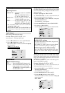
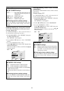
3. Use the ▲ and ▼ buttons to select “PLE LINK”.
4. Use the
ᮤ
and
ᮣ
buttons to select “ON”, then press the
MENU/ENTER button.
The mode switches as follows each time the
ᮤ
or
ᮣ
button is pressed:
OFF ↔ ON
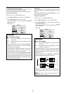
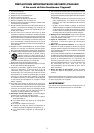
VIDEO WALL
EXIT
DIVIDER
POSITION
DISP. MODE
AUTO ID
IMAGE ADJUST
P. ON DELAY
PLE LINK
REPEAT TIMER
: 1
: SPLIT
: OFF
: OFF
: ON
: OFF
SEL.
RETURN
ADJ.
Information
Ⅵ PLE LINK settings
ON ...... Sets a uniform brightness for each screen in a
video wall.
OFF .... Sets the individual screen brightness for each
screen in a video wall.
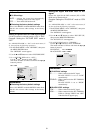
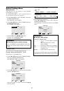
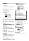
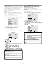
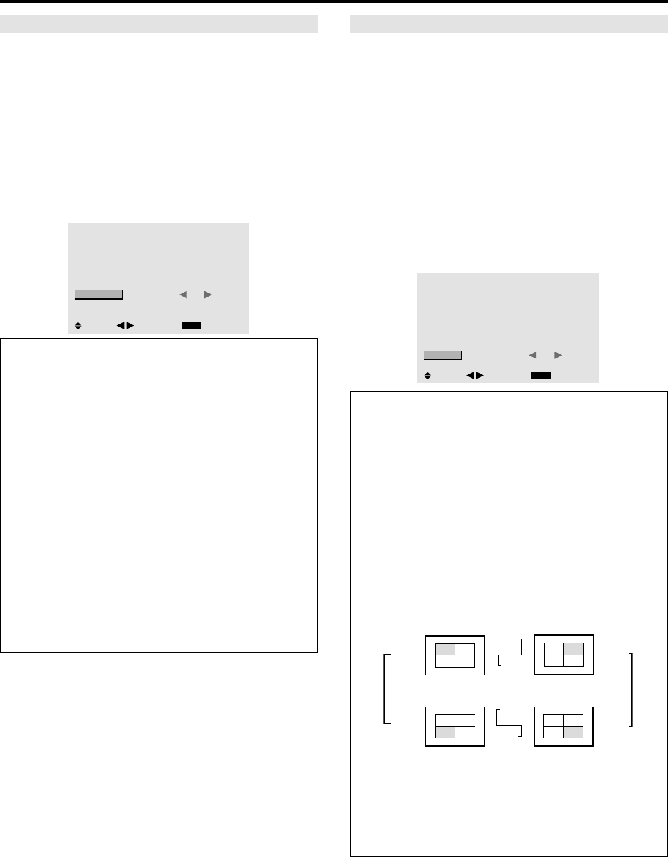
* When this function is set “ON”, connect your plasma
displays with the remote cable (optional) in the order of
the position numbers for the 2×2 video wall. See the
drawing below.
* If there are changes in the DIVIDER or POSITION,
the PLE LINK will automatically turn OFF.
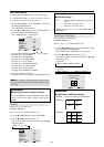
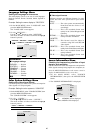
* With the 3×3 video wall, connect the final display to
the first display the same way as with 2×2 video wall.
Note:
The remote control can be operated unless the
IR REMOTE is set to “OFF”.
REMOTE
IN
REMOTE
IN
REMOTE
OUT
REMOTE
OUT
REMOTE
IN
REMOTE
OUT
REMOTE
OUT
REMOTE
IN
No.1
No.2
No.3No.4
No.1
No.2
No.3No.4
No.1
No.2
No.3No.4
No.1
No.2
No.3No.4
Display 1
Display 2
Display 4
Display 3