


24
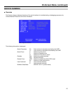
On-Screen Menu (continued)
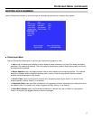
IMD CONFIGURATION SUBMENU (continued)
■
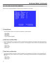
Tally Source
The V-R653-IMD-TE tally (OSD and LED) can be controlled in a variety of different ways. Use the Tally Source setting
to choose how tally is controlled:
Standard
Use the Standard setting to control tally via contact closure on the HD-15 tally interface.
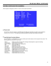
Image Video HW
Use the Image Video HW setting to control Image Video tally states via contact closure on the HD-15 tally
interface. Contact closure of the Red pin corresponds to Image Video Tally 1, and the Green pin maps to Image
Video Tally 2. This mode requires the IMD Tally Mode parameter to be set. Consult Image Video documentation
for further information.
Image Video 422
Use the Image Video 422 setting to control Image Video tally states via the Image Video serial protocol. LED and
OSD tally will be disabled in this mode, as Image Video tally states are manifested in the text color and other
parameters. This mode requires the IMD Tally Mode parameter to be set. Consult Image Video documentation for
further information.
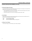
Standard + IV422
Use the Image Video 422 setting to control Image Video tally states via the Image Video serial protocol, while
controlling LED and OSD tally using contact closure on the HD-15 tally interface. This mode requires the IMD
Tally Mode parameter to be set. Consult Image Video documentation for further information.
TSL/MEl 422
Use the TSL/Marshall 422 setting to control OSD and LED tally via the TSL or Marshall serial protocols.
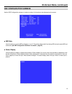
■
IMD Tally Mode
Use this setting when using Image Video tally control. Choose one of the following states, in conjunction with the
Image Video controlling device. T1, T2, T1T2, T2T1, T1-, T2-, T1T2-, T2T1-. Consult Image Video documentation for
further information.