


7-3
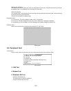
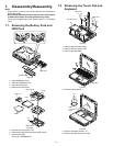
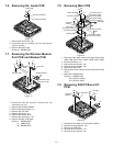
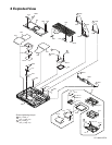
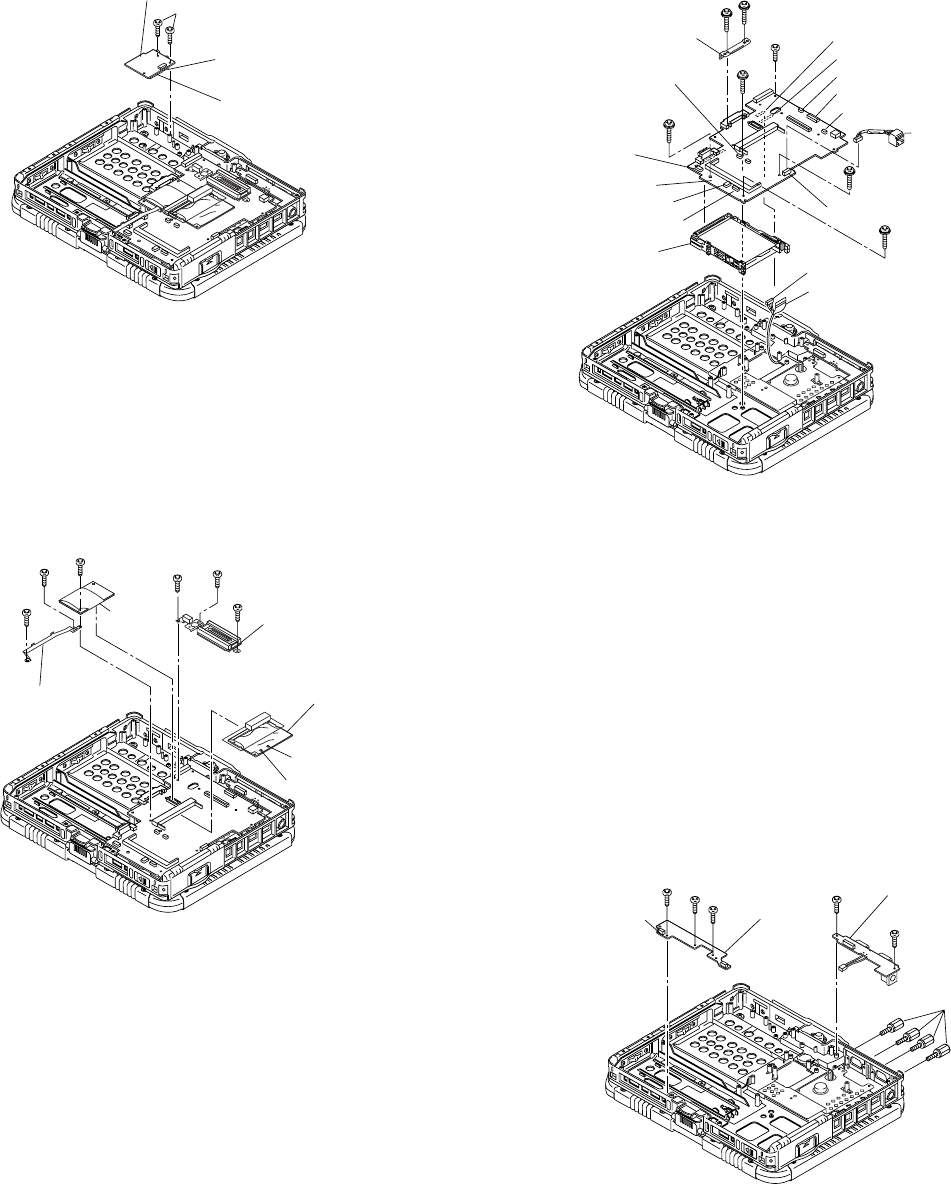
7.6. Removing the Audio PCB
Figure 10
1. Remove the two Screws. <H>
2. Disconnect the two Cables from two Connectors
(CN701, CN702).
3. Remove the Audio PCB.
Screw<H>: DRSB2+5FKL
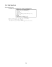
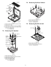
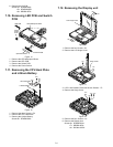
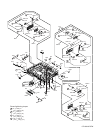
7.7. Removing the Wireless Module,
Port PCB and Modem PCB
Figure 11
1. Disconnect the two Antenna Cables from two
Connectors (J5, J6).
2. Remove the Wireless Module.
3. Remove the three Screws. <I>
4. Remove the Port PCB.
5. Remove the Screw. <J>
6. Remove the Modem PCB.
7. Remove the two Screws. <K>
8. Remove the BAT CON angle.
Screw<I>: DRSB2+5FKL
<J>: XSB2+4FNL
<K>: DRSB2+5FKL
<K>
<J>
<K>
<I>
<I>
Bat Con Angle
Connector (J5)
Connector (J6)
Modem
PCB
Port PCB
Wireless Module
<I>
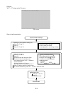
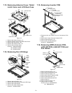
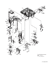
7.8. Removing Main PCB
Figure 12
1. Disconnect the eight Cables from eight Connectors
(CN3, CN9, CN12, CN14, CN23, CN30, CN35, CN36).
2. Remove the Screw. <L>
3. Remove the two Screws. <M>
4. Remove the four Screws. <N>
5. Remove the Main PCB.
6. Disconnect the two Cables from two Connectors (CN8,
CN17).
7. Remove the PCMCIA Unit.
Screw<L>: DRSB2+5FZL
<M>: DXYN2+J12FNL
<N>: DXYN2+J18FN
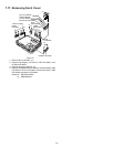
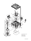
7.9. Removing PAD PCB and I/O
PCB
Figure 13
1. Disconnect the Cable from Connector (CN801).
2. Remove the three Screws. <O>
3. Remove the PAD PCB.
4. Remove the four Screws. <P>
5. Remove the two Screws. <Q>
Connector (CN702)
Connector (CN701)
Audio PCB
<H>
<L>
<M>
<M>
<N>
<N>
<N>
<N>
HDD Guid Plate
Connector (CN36)
Connector (CN35)
Connector (CN30)
PCMCIA Unit
to Connector (CN17)
Connector (CN3)
Connector (CN17)
Connector (CN8)
Connector (CN9)
Connector (CN14)
Connector (CN12)
LAN Cable
Main PCB
to Connector (CN8)
Connector
(CN23)
<O>
<O>
<O>
<Q>
<P>
<Q>
I/O PCB
PAD PCB
Connector
(CN801)