


7-5
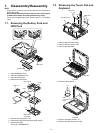
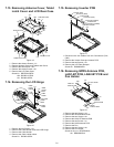
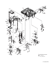
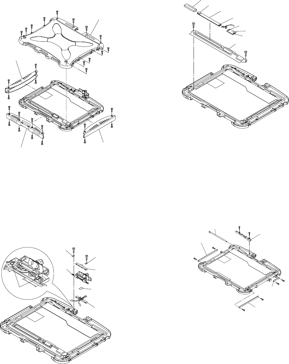
7.13. Removing Antenna Cover, Tablet
Latch Cover and LCD Rear Case
Figure 19
1. Remove the sixteen Screws. <V>
2. Remove Antenna Cover and Tablet Latch Cover.
3. Remove the two Screws. <W>
4. Remove the eleven Screws. <X>
5. Remove the LCD Rear Case.
Screw<V>: DRQT26+D5FKL
<W>: DXYN3+J10FNL
<X>: DXYN2+J6FNL
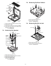
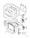
7.14. Removing the LCD Hinge
Figure 20
1. Remove the two Screws. <Y>
2. Remove the Cable Holder Plate and LCD Hinge.
3. Remove the Cable Holder.
4. Remove the Cable Holder sheet.
Screw<Y>: DXYN3+J8FNL
<Z>
<Z>
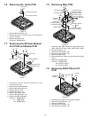
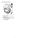
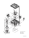
Inverter Case
Connector (CN2)
Connector (CN1)
Inverter PCB
TS PS2 PCB
Connector (CN901)
Connector (CN900)
LCD Back Damper
7.15. Removing Inverter PCB
Figure 21
1. Disconnect the two Cables from two Connectors (CN1,
CN2).
2. Remove the Inverter Case and Inverter PCB.
3. Remove the two Screws. <Z>
4. Remove the LCD Rear Damper.
Screw<Z>: DXHM0042ZA
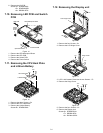
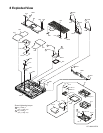
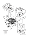
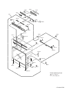
7.16. Removing GPRS Antenna PCB,
LAN1-BT PCB, LAN2-BT PCB and
Pen Holder
Figure 22
1. Remove the two Screws. <a>
2. Remove the GPRS Antenna PCB.
3. Remove the two Screws. <b>
4. Remove the LAN1-BT Antenna PCB.
5. Remove the two Screws. <c>
6. Remove the LAN2 Antenna PCB.
7. Remove the Pen.
8. Remove the two Screws. <d>
9. Remove the Pen Holder.
Screw<a><b><c>: DFHE5025XA
<d>: DRHM5025YA
<Y>
<Y>
LCD Cable
Holder
Sheet
Cable
Holder
Cable
Holder
Cable
Holder
Plate
Cable Holder
Plate
Cable
Holder
Plate
LCD
Hinge
<X>
<X>
<X>
<X>
<X>
<W>
<W>
<X>
<X>
<X>
<X>
<X>
<X>
<V>
<V>
<V>
<V>
<V>
<V>
<V>
<V>
Antenna Cover
Tablet Latch Cover
LCD Rear Case
Antenna Cove
r
<V>
<V>
<V>
<V>
<V>
<V>
<V>
<V>
<d>
<b>
<c>
<c>
<a>
<a>
<b>
<d>
Pen Holder
LAN1-BT
Antenna PCB
LAN2-BT
Antenna PCB
GPRS
Antenna PCB
Pen