


Reference Design HFRD-34.0 (Rev.3, 05/08) Maxim Integrated Products
Page 13 of 18
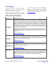
CM 3 Default
Sets the default configuration for the reference design
(Audio/Video/USB In1 to Audio/Video/USB Out1;
Audio/Video/USB In2 to Audio/Video/USB Out2, etc.)
CM 4 Demo Mode
Puts the reference design into a demonstration mode. When in this
mode, the controller will loop through the default and saved
configurations at a preset time interval. This operation allows for
automatic switching of the DVI and audio signals. Please note: The
USB configuration is not switched in demo mode (only DVI and
Audio).
CM 5 Main Menu
Return to Main Menu
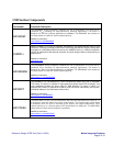
VSM 1 DVI Out1
Allows the user to switch DVI output 1 to any DVI input (1 through
4). The current switch selection is highlighted.
VSM 2 DVI Out2
Allows the user to switch DVI output 2 to any DVI input (1 through
4). The current switch selection is highlighted.
VSM 3 DVI Out3
Allows the user to switch DVI output 3 to any DVI input (1through
4). The current switch selection is highlighted.
VSM 4 DVI Out4
Allows the user to switch DVI output 4 to any DVI input (1through
4). The current switch selection is highlighted.
VSM 5 Main Menu
Return to Main Menu
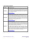
ASM 1 HeadphoneOut1
Allows the user to switch headphone output 1 to any audio input (1
through 4). The current switch selection is highlighted.
ASM 2 HeadphoneOut1
Allows the user to switch headphone output 2 to any audio input (1
through 4). The current switch selection is highlighted.
ASM 3 Line Out1
Allows the user to switch line output 1 to any audio inp
ut (1 through
4). The current switch selection is highlighted.
ASM 4 Line Out2
Allows the user to switch line output 2 to any audio input (1 through
4). The current switch selection is highlighted.
ASM 5 Main Menu
Return to Main Menu
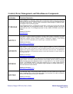
USM 1 USB HUB1 Out
Allows the user to switch USB hub 1 to any USB input (1 through
4). The current switch selection is highlighted. Note: Fanout is not
supported in the USB switch.
USM 2 USB HUB2 Out
Allows the user to switch USB hub 2 to any USB input (1 through
4). The current switch selection is highlighted. Note: Fanout is not
supported in the USB switch.
USM 3 USB HUB3 Out
Allows the user to switch USB hub 3 to any USB input (1 through
4). The current switch selection is highlighted. Note: Fanout is not
supported in the USB switch.
USM 4 USB HUB4 Out
Allows the user to switch USB hub 4 to any USB input (1through 4).
The current switch selection is highlighted. Note: Fanout is not
supported in the USB switch.
USM 5 Main Menu
Return to Main Menu
ACM 1 HP1 Volume
Allows the user to adjust headphone 1 output volume (1 through 7).