


Reference Design HFRD-34.0 (Rev.3, 05/08) Maxim Integrated Products
Page 15 of
18
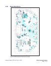
8 Schematics, Component List,
and Layout Drawings
The full schematics, component list, and PCB
layout drawings are available to download in PDF
format at:
http://www.maxim-
ic.com/tools/other/appnotes/4232/4232_softwar
e.zip.
See sections 10 and 11 for additional details
regarding the use of the schematics and layout
drawings for new designs.
9 Gerber Files and Firmware
The Gerber files and firmware assist design
engineers in developing their projects, and are
available to Maxim customers upon request. See
sections 10 and 11 for additional details regarding
the use of Gerber files and firmware. To receive
the Gerber or firmware files, please send an email
to
StrategicApps@maxim-ic.com with HFRD-
34.0 in the subject line. Include the following
information:
1. Your name
2. Company name
3. Company website
4. Brief description of your project
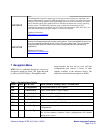
10 Design Notes
Please review the following design notes:
1. Line Out1 and Line Out2 are designed to
drive an audio line impedance (> 1kΩ)
with typical line-out voltage levels. These
two audio outputs can be optimized to
drive headphone loads by changing
external component values. See the
MAX9728 data sheet for additional
information.
2. The USB hub controllers (U26, U27,
U36, and U39) have configurations and
settings that can be adjusted through a 2-
wire bus controlled by the C. Currently
these features and configurations are set
through the C firmware.
3. The USB HUB reset connection for the
four HUBs (pin 26 of USB2512 and
USB2513 devices) are tied together on the
current version of the reference design.
Splitting these connections to have
individual control will improve the
overall USB switching operation.
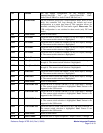
4. If desired, U47 (MAX3420) is provided
to facilitate control of the switch through
a USB interface. Currently these features
are not preprogrammed into the reference
design.
5. USB HUB 4 is a self-powered HUB
(power is drawn from the HFRD-34.0
supply). USB HUBs 1-3 are powered
from the host. All USB HUBs include
overcurrent shutdown protection.
6. It is recommended that you increase the
supply filtering (i.e., add series inductance
and bulk capacitance) of the host USB
power supplies (for HUBs 1-3) in order to
reduce crosstalk from the USB power-
supply noise to the audio outputs.
7. The power MOSFET transistors (Q2-
Q13) used for switching the USB host
power are flipped over due to a layout
error in the pin order. When copying this
section of the design, the transistor
footprint should be corrected.
8. The ATMEL C (U49, ATMEGA168)
can be in-circuit reprogrammed to
perform custom features. Use the
AVRISP-MKII programmer and the
connections provided through J15.
9. A 10kΩ pull-up resistor should be added
to pin 9 of the MAX3420 (U47) in any
design revisions.
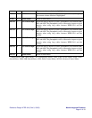
10. Connecting pins 14 and 16 together on
each DVI input will increase the