Evaluate: MAX1400/MAX1402
MAX1402 Evaluation Kit/Evaluation System
6 _______________________________________________________________________________________
For simplicity, the EV kit software assumes that all three
transfer functions are configured alike.
Detailed Description
________________________of Hardware
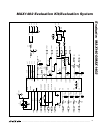
U1, the MAX1402, is a multichannel, high-resolution
A/D converter (refer to the MAX1402 data sheet). U2,
the MAX6025, is a 2.5V reference (refer to the
MAX6025 data sheet). Y1 contains a ceramic resonator
and its load capacitors. R1–R6 together with C3–C8
form anti-aliasing input filters. R8 and C11 filter the digi-
tal power supply. The analog supply comes through fil-
ter R7/C10.
Input Filtering
The EV kit has an RC filter on each input with a time
constant of approximately 0.01µs = 10ns (R = 100Ω,
C = 100pF). When scanning between channels, the RC
filter’s settling time may increase the acquisition time
required for full accuracy.
Evaluating the MAX1400
The MAX1400 can be evaluated by shorting across
jumpers JU6 and JU7. The MAX1400 is exactly like the
MAX1402, except that the function of pins 5, 6, 7, and 8
is changed. Instead of the OUT1/OUT2 outputs and
DS0/DS1 inputs, these pins are used to provide access
to the analog signal between the multiplexer and the
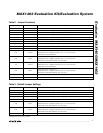
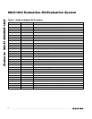
A/D converter. Tables 2 and 3 list the jumper functions
and default settings. Refer to the MAX1400 data sheet
for detailed information.
Measuring Supply Current
Supply current can be estimated by measuring the volt-
age across a series resistor. On the EV kit board, the
MAX1402 draws all of its analog and digital power
through R8, which is 10Ω. In addition, all analog supply
current flows through R7, which is also 10Ω.
Troubleshooting
Problem: unacceptable amounts of noise in the signal.
Collect a sample of 1024 measurements at a 60Hz data
rate. Observe whether the problem is caused by 60Hz
noise.
Any AC-powered equipment connected to the analog
signal ground can inject noise. Try replacing AC-pow-
ered DVMs with battery-powered DVMs.


