


Installation
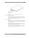
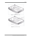
3-6 Maxtor QuickView 400/500GB Serial ATA Hard Disk Drive
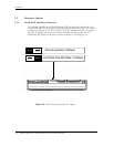
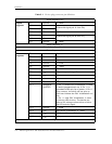
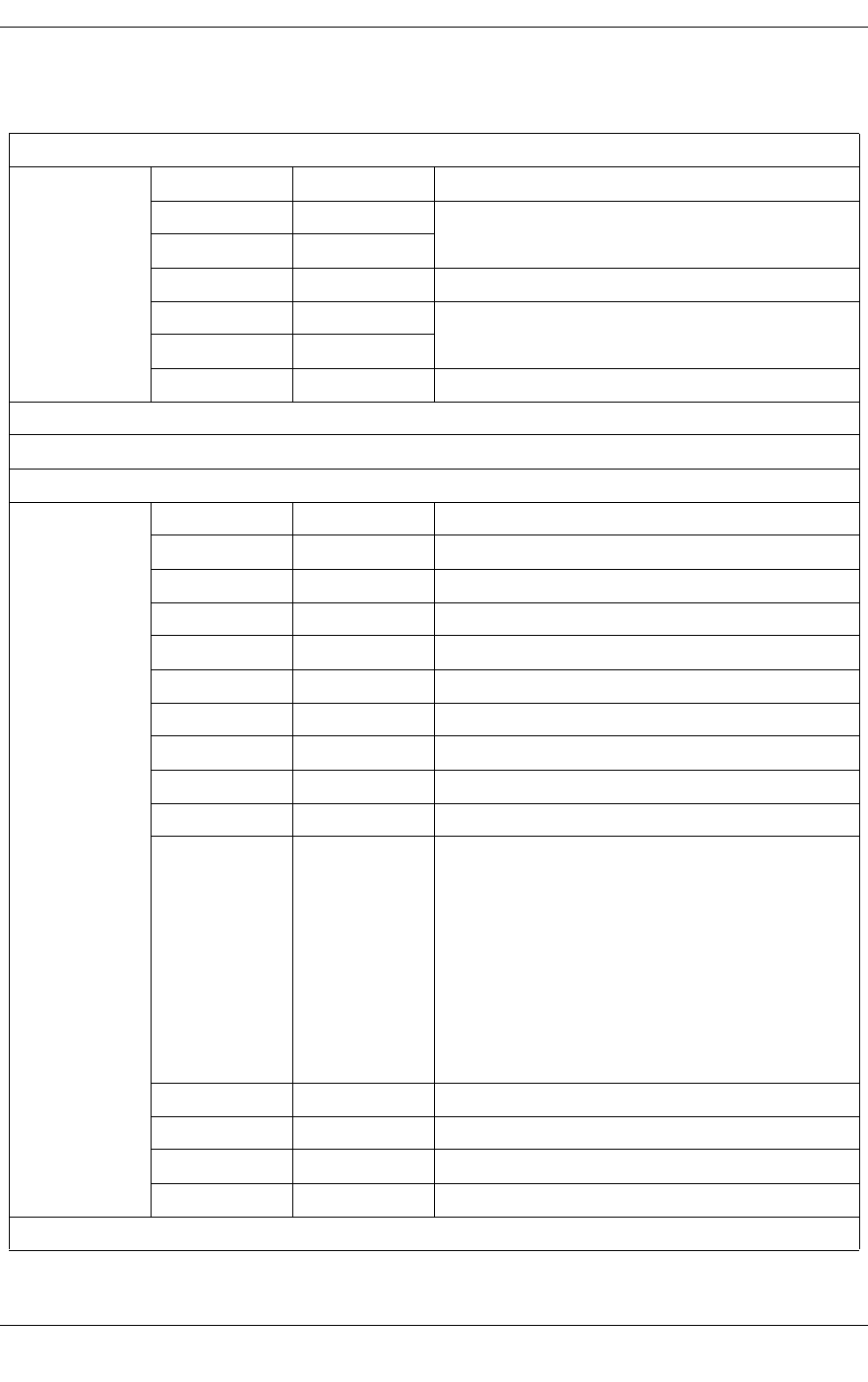
Table 3-1 Device plug connector pin definition
Signal Segment Key
Signal
segment
S1 Ground 2
nd
Mate
S2 A+
Differential signal pair A from Phy
S3 A-
S4 Ground 2
nd
Mate
S5 B-
Differential signal pair B from Phy
S6 B+
S7 Ground 2
nd
Mate
Signal Segment “L”
Central Connector Polarizer
Power Segment “L”
Power
segment
P1 Open
P2 Open
P3 Open
P4 Ground 1
st
mate
P5 Ground 2
nd
mate
P6 Ground 2
nd
mate
P7 V
5
5V power, pre-charge, 2
nd
mate
P8 V
5
5V power
P9 V
5
5V power
P10 Ground 2
nd
mate
P11 Staggered
Spin/LED
1. Pin 11, before PHY initialization, is used
to detect staggered spin up. If Pin 11 is
grounded Drives spin up on power. If Pin 11
is no-connect, the drive will not spin up
until host initiates the PHY initialization rou-
tine.
2. Pin 11, after PHY initialization, is used
for driving LED Activity. The device pro-
vides a low voltage-current driver to drive
the LED activity signal.
P12 Ground 1
st
mate
P13 V
12
12V power, pre-charge, 2
nd
mate
P14 V
12
12V power
P15 V
12
12V power
Power Segment Key