


SATA Bus Interface and ATA Commands
Maxtor QuickView 400/500GB Serial ATA Hard Disk Drive 5-1
Chapter 5
SATA BUS INTERFACE AND ATA COMMANDS
This chapter describes the interface between the QuickView Serial ATA 400/500GB
hard disk drive and the ATA bus. The commands that are issued from the host to
control the drive are listed, as well as the electrical and mechanical characteristics of
the interface.
5.1 INTRODUCTION
The Maxtor QuickView Serial ATA 400/500GB hard disk drive uses the standard
ATA/ATAPI-7 interface. Support of various options in the standard are explained
in the following sections.
5.2 MECHANICAL INTERFACE
5.2.1 Signal Cable and Connector
The Maxtor QuickView Serial ATA 400/500GB hard disk drive contains unitized
connector for both signal and power connections. The dimensions and
specifications of the unitized connector comply with clause 14 in the ATA/
ATAPI-7 standard.
5.3 ELECTRICAL INTERFACE
5.3.1 ATA Bus Interface
5.3.1.1 Electrical Characteristics
Signals on the SATA interface are assigned to connector pins according to clause 14
in the ATA/ATAPI-7 standard. The signaling protocol complies with clause 15-17 of
the standard.
5.4 REGISTER ADDRESS DECODING
The Maxtor QuickView Serial ATA 400/500GB hard disk drive allow their host
systems to address the full set of command and control registers as specified in clause
5 of the ATA/ATAPI-7 standard.
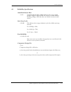
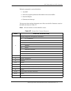
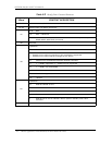
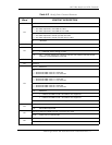
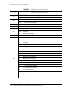
5.5 COMMAND INTERFACE
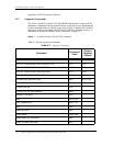
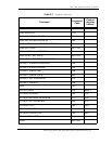
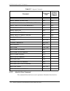
5.5.1 General Feature Set
The µProcessor, Disk Controller, and ATA Interface electronics are contained in a