


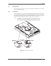
Installation
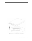
Maxtor DiamondMax 8S 40GB SATA 4-11
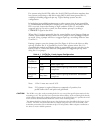
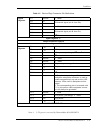
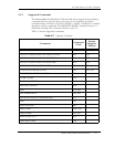
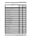
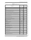
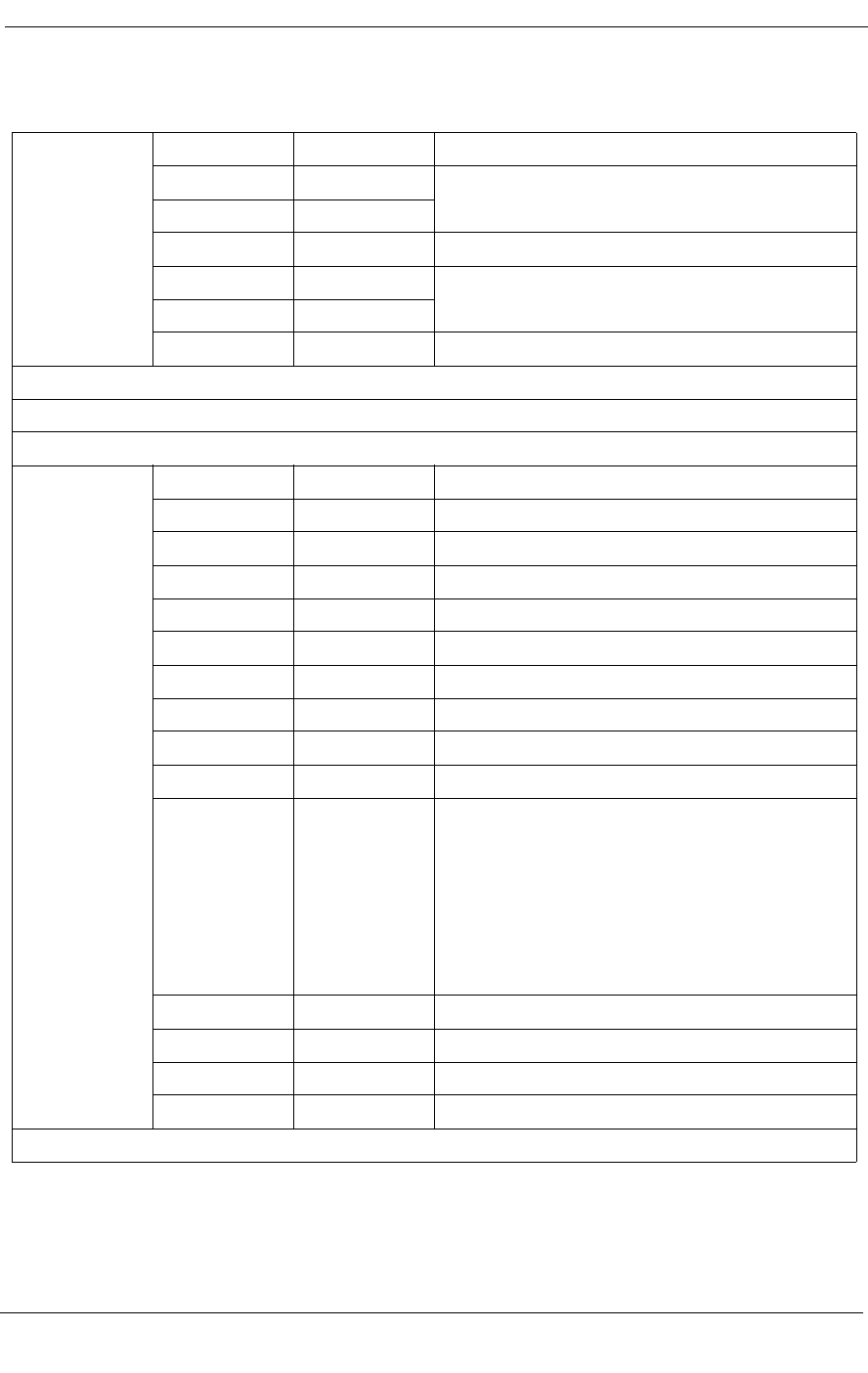
Table 4-2 Device Plug Connector Pin Definitions
Note 1. 3.3V power is not used by DiamondMax 8S 40GB SATA
Signal
Segment
S1 Ground 2
nd
Mate
S2 A+
Differential signal pair A from Phy
S3 A-
S4 Ground 2
nd
Mate
S5 B-
Differential signal pair B from Phy
S6 B+
S7 Ground 2
nd
Mate
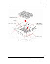
Signal Segment “L”
Central Connector Polarizer
Power Segment “L”
Power
Segment
P1 V
33
3.3V power
1
P2 V
33
3.3V power
1
P3 V
33
3.3V power, pre-charge, 2
nd
mate
1
P4 Ground 1
st
mate
P5 Ground 2
nd
mate
2
P6 Ground 2
nd
mate
P7 V
5
5V power, pre-charge, 2
nd
mate
P8 V
5
5V power
P9 V
5
5V power
P10 Ground 2
nd
mate
P11 Reserved 1. The pin corresponding to P11 in the
backplane receptacle connector is used to
enable staggered spin-up and activity LED
features, when used in backplane enviro-
ments.
2. The corresponding pin to be mated with
P11 in the power cable receptacle connec-
tor will always be grounded.
P12 Ground 1
st
mate
P13 V
12
12V power, pre-charge, 2
nd
mate
P14 V
12
12V power
P15 V
12
12V power
POWER SEGMENT KEY