


Installation
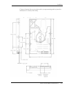
Maxtor DiamondMax 8S 40GB SATA 4-12
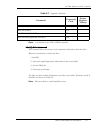
Note 2. Host system should ground P4,P5, and P6. Failure to do so may cause
improper drive operation.
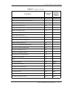
The following points should be noted:
All pins are in a single row, with a 1.27 mm (.050”) pitch.
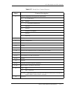
• The comments on the mating sequence apply to the case of
backplane blind mate connector only. In this case, the mating
sequences are: (1) the ground pins P4 and P12; (2) the pre-
charge power pins and the other ground pins; and (3) the
signal pins and the rest of the power pins.
• There are three power pins for each voltage. One pin from
each voltage is used for pre-charge in the backplane blind-
mate situation.
• If a device uses 3.3 V, then all V
33
pins must be terminated.
Otherwise, it is optional to terminate any of the V
33
pins. If a
device uses 5.0 V, then all V
5
pins must be terminated.
Otherwise, it is optional to terminate any of the V
5
pins.
• If a device uses 12.0 V, then all V
12
pins must be terminated.
Otherwise, it is optional to terminate any of the V
12
pins.
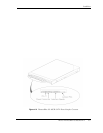
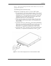
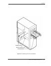
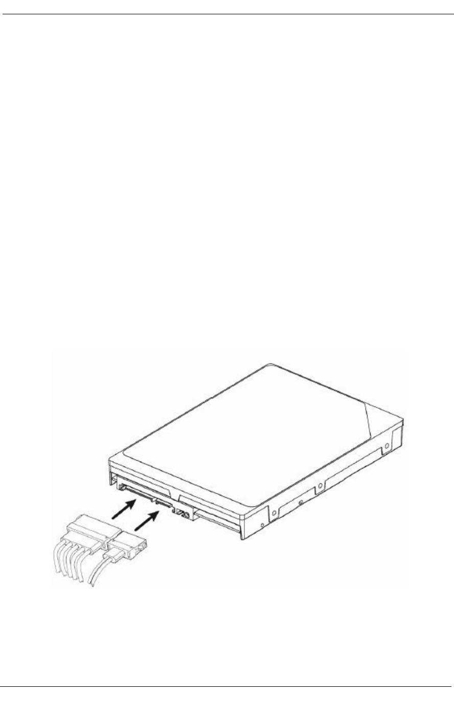
Figure 4-7 Drive Power Supply and SATA Bus Interface Cables