5
2
ALL VEHICLES
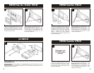
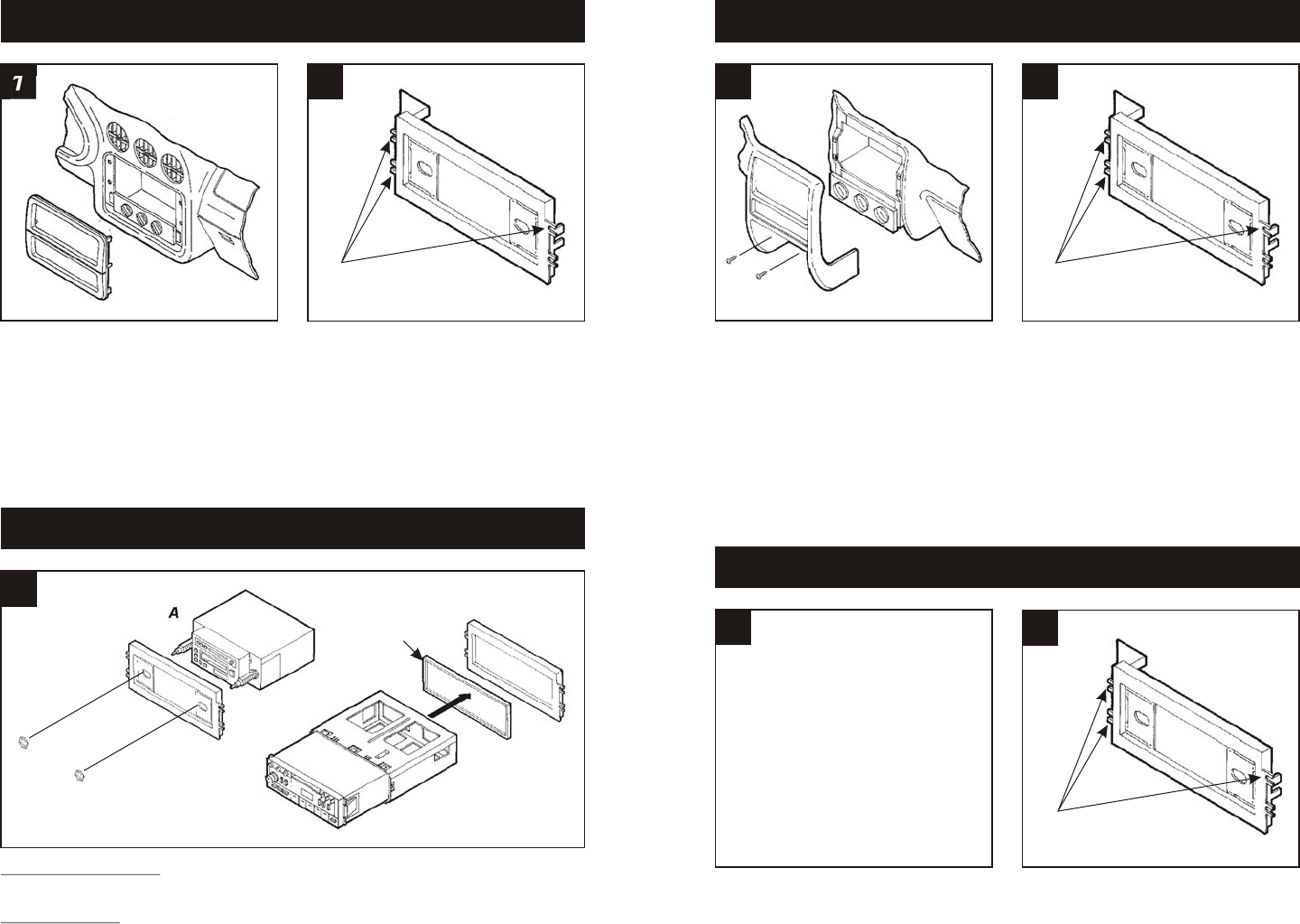
2-SHAFT HEAD UNITS: Slide the aftermarket head unit into the kit and secure with shaft
nuts. (see Fig. A)
DIN HEAD UNITS: Insert the Spacer* into the Radio Housing. Slide the DIN cage into the kit
and secure by bending the metal locking tabs down. Slide the aftermarket head unit into the
cage until secure. (see Fig. B)
3
Fig. A
Fig. B
*OPTIONAL
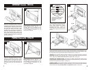
Disconnect the negative battery terminal to
prevent an accidental short circuit. Remove
(2) Phillips screws from the pocket. Remove
(2) Phillips screws above the instrument
cluster. Unclip the dash trim bezel and
remove. Remove (3) 7mm hex-head
screws securing the factory head unit and
disconnect the wiring.
1
PONTIAC Grand Am 1996-98
2
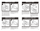
Disconnect the negative battery terminal to
prevent an accidental short circuit. Unclip
the radio trim bezel. Remove (3) 9/32"
screws securing the factory head unit and
disconnect the wiring.
1
PONTIAC Grand Am 1999-00
2
Disconnect the negative battery terminal to
prevent an accidental short circuit. Unclip
the radio trim bezel. Remove (4) 7mm hex-
head screws securing the factory head unit
and disconnect the wiring.
1
PONTIAC Trans Am / Firebird 1994-02
2
"C"
"C"
"C"
Illustration not
available when
printed
Cut and remove all mounting tabs on the
Radio Housing EXCEPT tabs "C". The
mounting tabs can be identified by the
stamped letter on the back of each tab. Skip
to the Installation Instructions for ALL
VEHICLES on Page #5.
Cut and remove all mounting tabs on the
Radio Housing EXCEPT tabs "C". The
mounting tabs can be identified by the
stamped letter on the back of each tab. Skip
to the Installation Instructions for ALL
VEHICLES on Page #5.
Cut and remove all mounting tabs on the
Radio Housing EXCEPT tabs "C". The
mounting tabs can be identified by the
stamped letter on the back of each tab. Skip
to the Installation Instructions for ALL
VEHICLES on Page #5.


