


INSTALLATION OF THE STAND
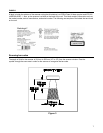
With the Metrologic stand (Part #45-45479), the scanner can be positioned in a vertical orientation. To use this
stand, four 6-32 x ½" machine screws and two #10 panhead wood screws will need to be purchased. The
maximum distance the screws should go into the scanner is ½ inch.
1. Lay the scanner face down on a clean cloth to prevent any scratches from occurring on the output
window. Position the scanner so the red and green LEDs are pointed toward you.
2. Lay the stand on top of the scanner with the angled bracket pointing up and toward you.
3. Align the four clearance holes to the four holes in the scanner’s case. Fasten the stand to the scanner
by inserting the four 6-32 x ½" screws into the four holes in the scanner’s case.
4. Drill two holes into the work surface that correspond with the holes in the 254 mm x 95 mm (10" x 3.75")
base of the stand.
5. Use the two #10 panhead wood screws to attach the stand and scanner to the work surface.
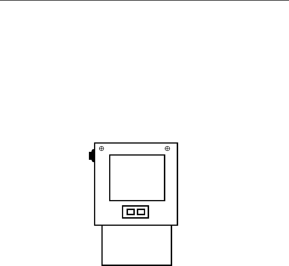
(Refer to Figure 1)
Figure 2
5