6
INSTALLATION
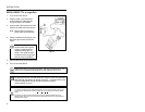
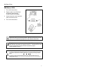
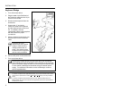
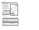
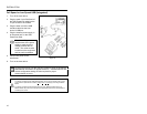
RS232, RS232 TTL or Light Pen
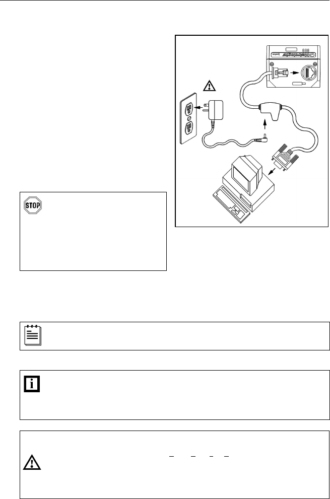
1. Turn off the host device.
2. Plug the male 10-pin RJ45 end
of the PowerLink cable into the
10-pin socket on the IS3480.
3. Connect the 9-pin female end of the
PowerLink cable to the host device.
Note: Skip to step 6 if receiving
power from the host device.
4. Plug the external power supply into
the power jack on the PowerLink
cable.
Check the AC input
requirements of the power
supply to make sure the
voltage matches the AC
outlet. The outlet must be
located near the equipment
and be easily accessible.
5. Connect AC power to the transformer.
6. Turn on the host device.
When the scanner first receives power, the blue LED will turn on; the
scanner will simultaneously beep once and flash the white LED.
Plugging the scanner into the serial port of the PC does not guarantee
that scanned information will appear at the PC. A software driver and
correct configuration setting are also required for proper
communication to occur.
Caution
To maintain compliance with applicable standards, all circuits connected to the scanner
must meet the requirements for SELV (Safety Extra Low Voltage) according to EN/IEC
60950.
To maintain compliance with standard CSA C22.2 No. 60950/UL 60950 and norm
EN/IEC 60950, the power source should meet applicable performance requirements for
a limited power source.
Figure 4.


