


7
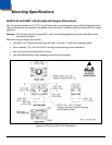
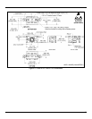
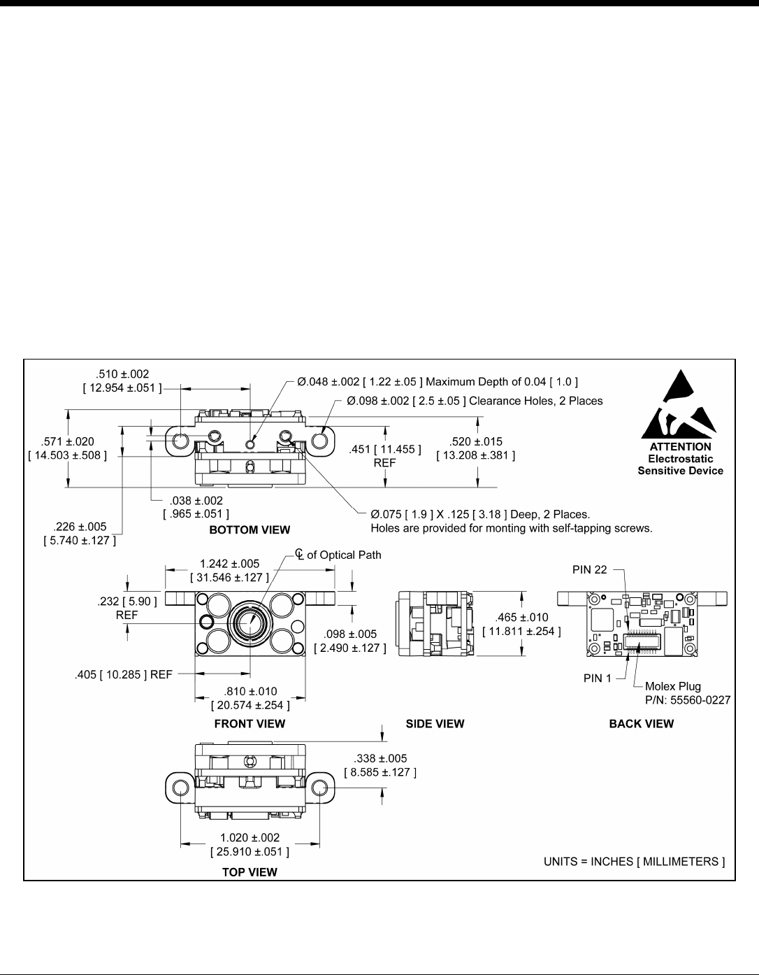
IS4910-01 / IS4911-01 Non-Decode Engine Dimensions
The -01 models include two Ø .075" [1.9 mm] blind holes for mounting the engine with self-tapping screws.
Two additional Ø .098" ± .002 [2.5 mm ±.05 mm] clearance holes are provided as a secondary mounting
option. The clearance holes are located on tabs that extend from the sides of the engine's chassis.
A keying location point is provided on the bottom of the engine to assist with alignment.
Warning: The limited warranty (on page 49) is void if the following recommendations are not adhered to when
mounting the engine.
When securing the engine with self-tapping screws:
• Use M2.2 x 4.5 Philips Pan Head, Type AB, Steel, Zinc Clear, Trivalent self-tapping screws.
• Do not exceed 1.75 +0.5 in-lb [2.02 +6 cm-kg] of torque during screw installation.
• Use a minimum mount thickness of 0.3 mm.
• Use safe ESD practices when handling and mounting the engine.
Figure 9. IS4910-01 / IS4911-01 Dimensions