


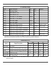
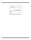
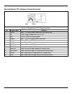
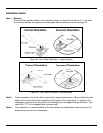
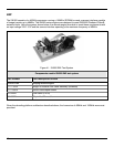
41
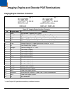
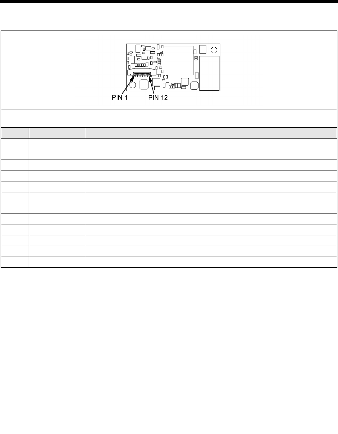
Decode Board (TTL) Output to Host Connector
Figure 35. Decode Board (TTL) Output Connector
Pin Signal Name Function
1 232INV Input: TTL RS232 polarity control with 32k ohm pull-up.
2 Vin Power: Supply voltage input (3V to 5.5V)
3 GND Ground: Power and signal ground.
4 (n)RxD Input: TTL Level RS232 Receive data input.
5 (n)TxD Output: TTL Level RS232 transmit data.
6 (n)CTS Input: TTL level Clear to Send.
7 (n)RTS Output: TTL level RS232 Request to Send.
8 PWRDWN Output: active high = IS4920 is in power down mode.
9 nBEEPER Output: active low signal capable of sinking current.
10 nGoodRead Output: active low signal for sinking current (Good Read).
11 nWAKE Input: Signal used to bring engine out of power-down.
12 nTrig Input: Signal used as trigger input to activate the IS4920