


17
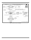
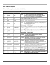
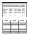
Host Interface Signals
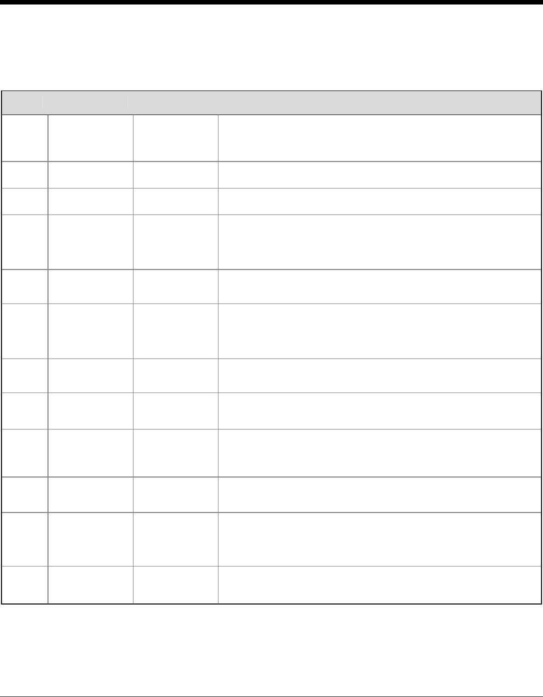
The host interface signals are described in the table below.
Pin# TTL RS232 USB Description
1 232INV NC
Input: TTL RS232 polarity control with 32k ohm pull-up.
Connect to ground for UART to UART signal polarity.
Pull up to Vin for standard TTL RS232 polarity.
2 V
in
V
in
Power: Supply voltage input (3V to 5.5V)
3 GND GND Ground: Power and signal ground.
4 (n)RxD D-
Input: TTL Level RS232 Receive data input, weak pull up to V
in
.
Polarity determined by Pin1
Bidirectional: USB D- Signal
5 (n)TxD <reserved>
Output: TTL Level RS232 transmits data. Polarity Determined
by Pin 1
6 (n)CTS D+
Input: TTL level Clear to Send, weak pull up to V
in
. Polarity
configurable via software
Bidirectional: USB D+ signal
7 (n)RTS <reserved>
Output: TTL level RS232 Request to Send. Polarity
configurable via software
8 PWRDWN PWRDWN
Output: Open drain, 100K pull up to V
in
; active high indicates
that the IS4920 is in Power Down Mode.
9 nBEEPER nBEEPER
Output: Open drain, 100K pull up to V
in
; active low signal
capable of sinking current. PWM controlled signal can
be used to drive an external beeper.
10 nGoodRead nGoodRead
Output: Open drain, 100K pull up to V
in
; active low signal for
sinking current of a Good Read LED circuit.
11 nWAKE nWake
Input: Weak pull up to V
in
; active low, the signal can be used to
bring the engine out of Power Down (TTL RS232 version
only) or Sleep Mode (TTL RS232 and USB versions).
12 nTrig nTrig
Input: Weak pull up to V
in
; active low, the signal can be used as
a trigger input to activate the IS4920.