


10
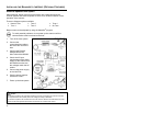
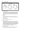
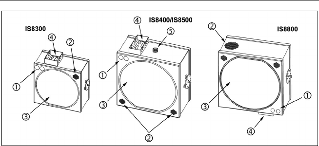
PARTS OF THE SCANNER
c
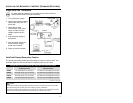
Green and Red LEDs
The red LED is on when the unit is done power up, the VLD is emitting light
and the unit is ready to scan. The green LED flashes when the scanner
has read a bar code successfully. The functions of the LED's can be
reversed through special configuration with the MetroSet
®
2
configuration
program. See the Visual and Audible Indicators section of this guide for
more details.
d
Speaker
The speaker is configured to emit a beep when a bar code has been
transmitted. The IS8800 has an additional 90 dB speaker location on the
side of the case.
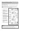
e
Laser Output Window
This aperture emits and receives laser light.
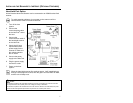
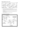
f
D-type Connector Area
This area contains four D-type male connectors, a 25-pin, 15-pin, and two
9-pin D-sub connectors. The 25-pin connector is designed to attach a
communication cable to the host device. The 15-pin connector is used to
attach two scanners as primary/secondary and/or to connect the MX001
industrial control interface to the scanner. The first 9-pin connector is used
to attach the power supply to the scanner and the second 9-pin connector
is used to attach a hand held 5V non-decode type scanner to the
HoloTrak
®
. Refer to Appendix C for Pinout details.
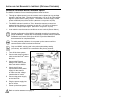
g
D-type Connector Area
The 8-pin Male AMP Connector is used to attach the optional MX008
external speaker box. Refer to Appendix C for Pinout details