


51
SCANNER AND CABLE TERMINATIONS
SCANNER PINOUT CONNECTIONS
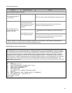
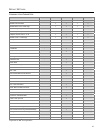
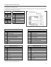
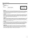
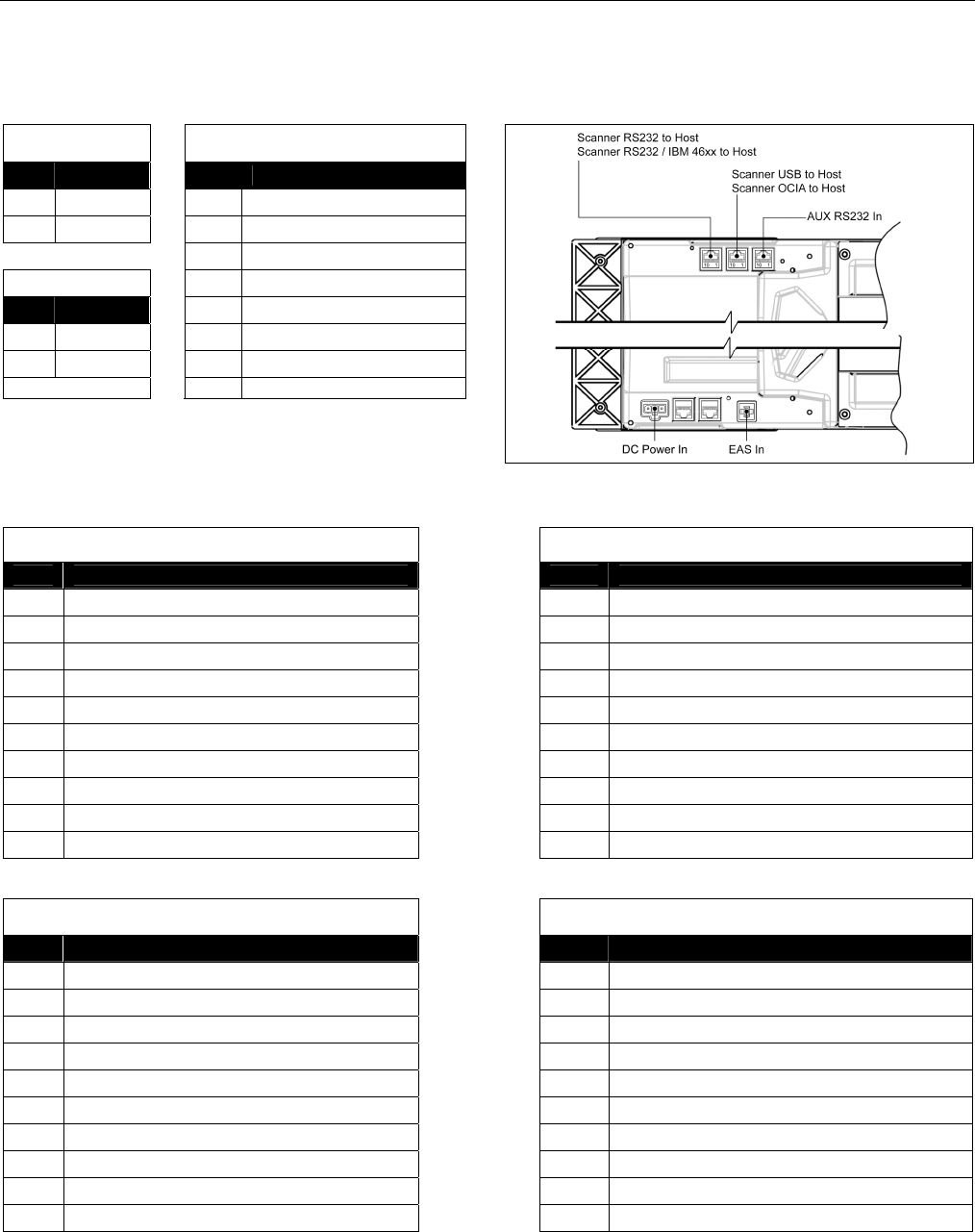
The StratosH scanner terminates to 10-pin modular jacks located on the bottom of the unit. The serial number label indicates
the model number and interface of the scanner.
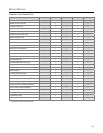
EAS
Auxiliary RS232 In
Pin Function
Pin Function
1 EAS In
1 Ground
2 EAS Out
2 RS232 Receive Input
3 RS232 Transmit Output
DC Power
4 RS232 RTS In
Pin Function
5 RS232 CTS Out
1 12VDC
6-8
No Connect
2 Ground
9 +5V Out
3 5.2VDC 10
No Connect
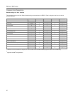
Figure 42. Connector Layout on the Bottom of the Scanner
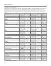
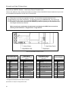
Scanner to Host, RS485
S
Scanner to Host, RS232
Pin Function Pin Function
1 Signal Ground 1 Signal Ground
2 RS232 TX Output 2 RS232 TX Output
3 RS232 RX Input 3 RS232 RX Input
4
Reserved for RS232 Interface
4 RS232 RTS Output
5
Reserved for RS232 Interface
5 RS232 CTS Input
6
Reserved for RS232 Interface
6 RS232 DTR Input
7 IBM B- 7
Reserved for IBM 46xx Interface
8 IBM B+ 8
Reserved for IBM 46xx Interface
9
No Connect
9
No Connect
10
No Connect
10
No Connect
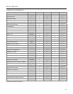
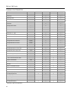
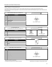
Scanner to Host, OCIA
Scanner to Host, USB
Pin Function Pin Function
1 Signal Ground 1 Signal Ground
2
Reserved
2 Reserved
3
Reserved
3 Reserved
4 R Data 4
Reserved for OCIA Interface
5 R Data Return 5
Reserved for OCIA Interface
6 Clock In 6 Data +
7 Clock Out 7 PC+5VDC
8 Clock In Return / Clock Out Return 8 Data -
9
No Connect
9
No Connect
10 Shield Ground 10 Shield Ground
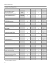
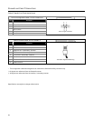
S
Applicable for IBM
®
Host applications
Specifications are subject to change without notice
.